
Bucket holding apparatus and associated method

Inactive Publication Date: 2010-05-04
PETRASHUNE CHRIS +2
View PDF5 Cites 17 Cited by
  • Summary
  • Abstract
  • Description
  • Claims
  • Application Information

AI Technical Summary

Benefits of technology

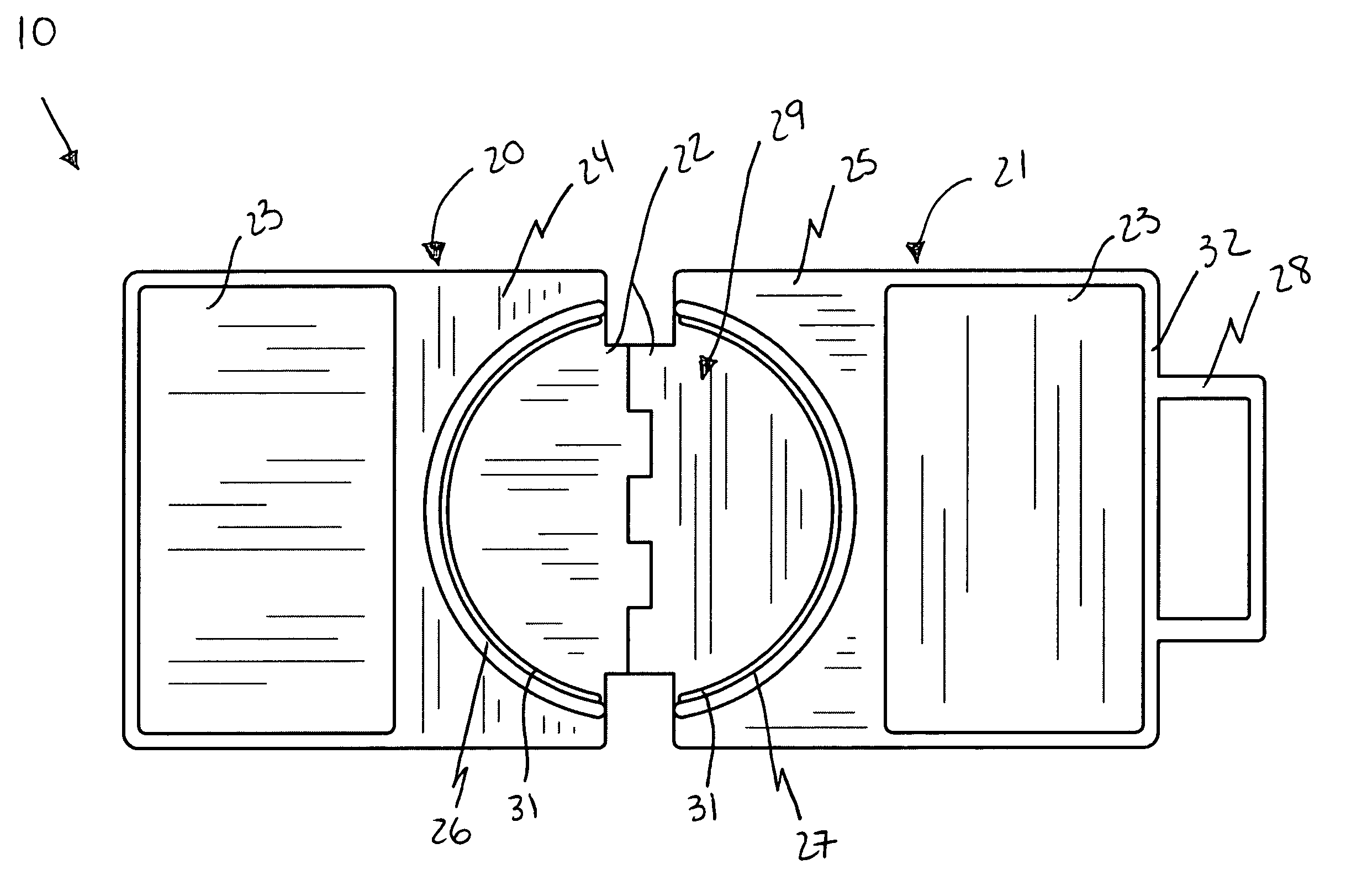
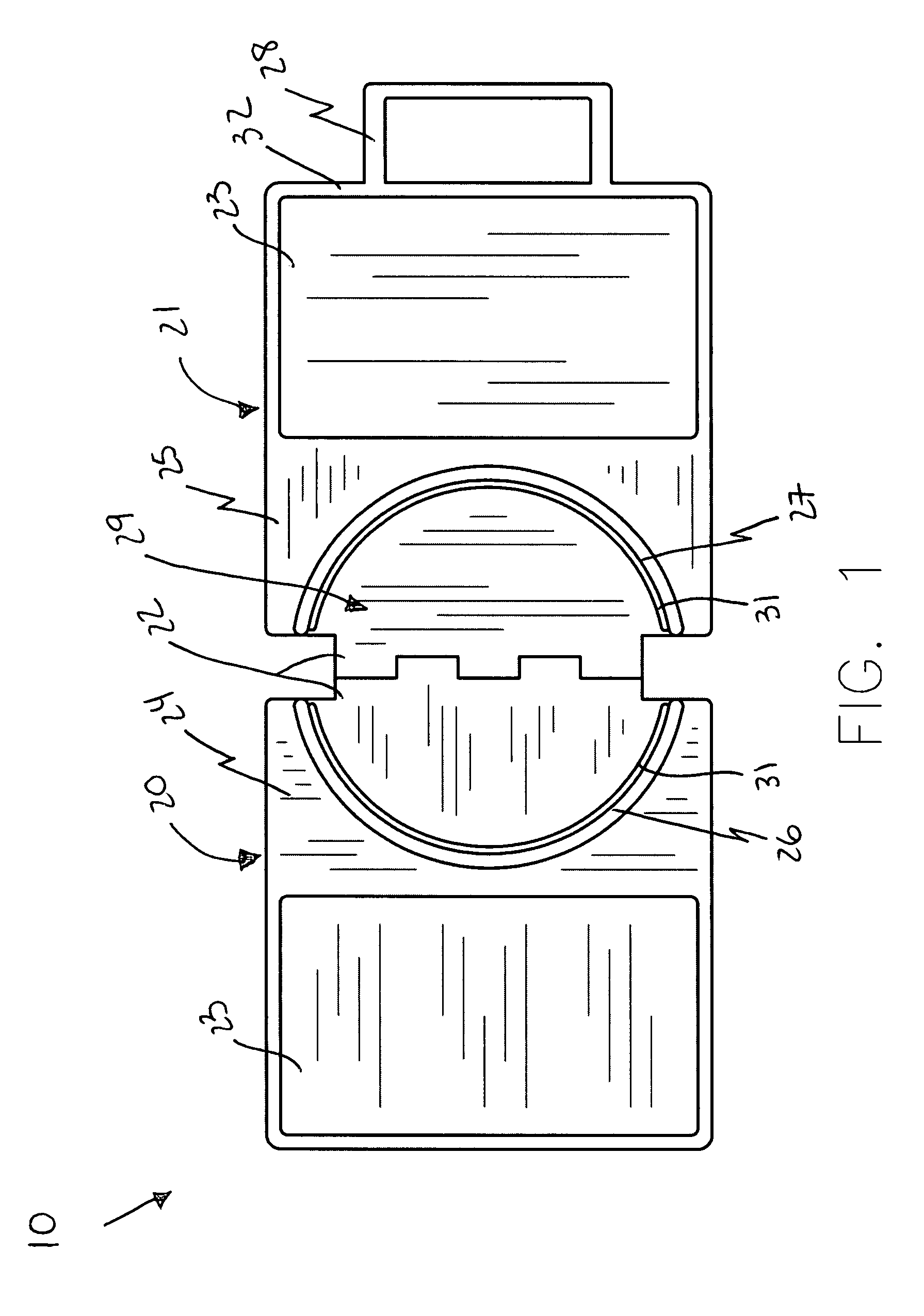
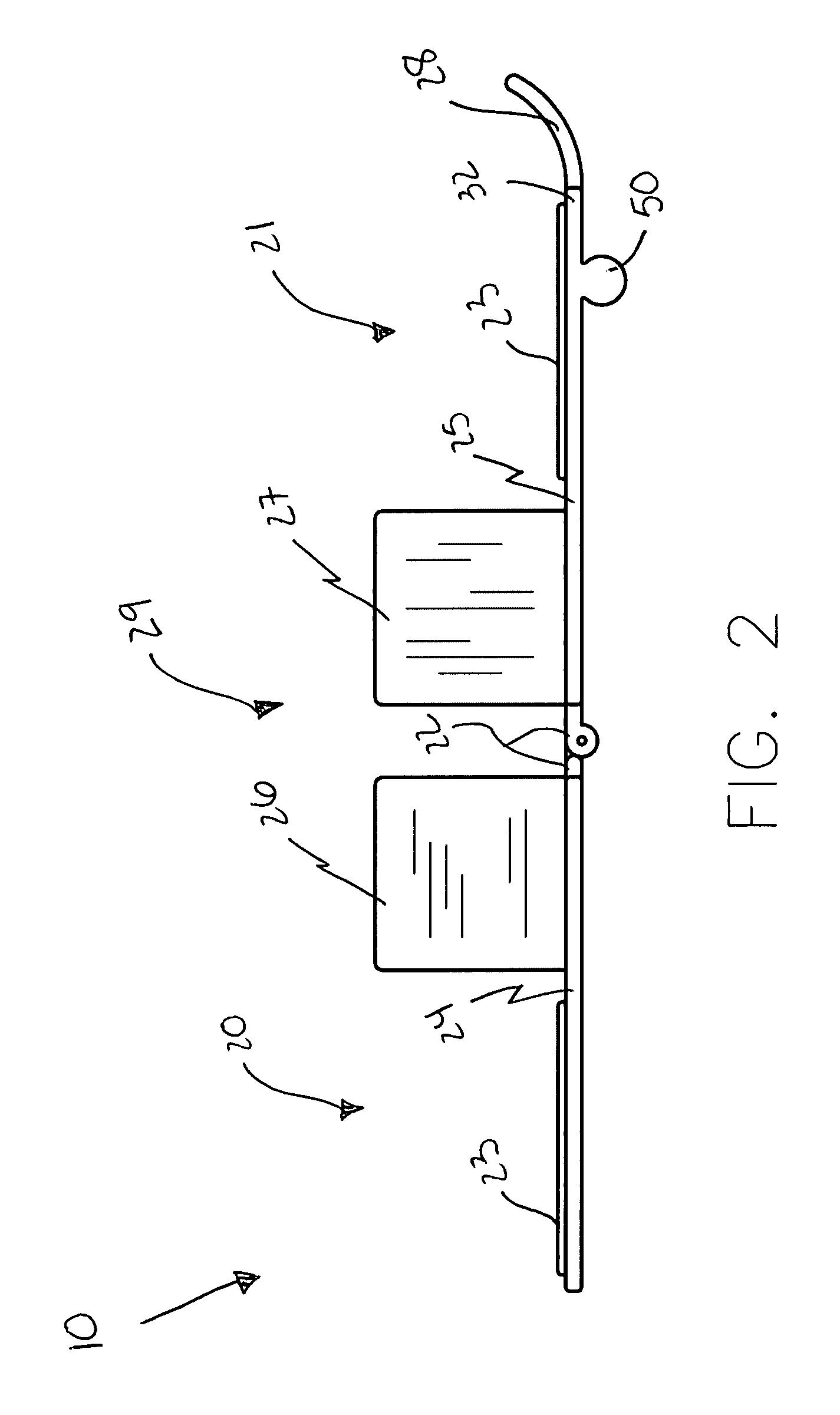
[0018]The bucket holding apparatus further includes an arcuate lever directly and statically conjoined to the second carriage and extending laterally upwards away from an outer edge thereof. The first and second carriages are effectively pivoted about the fulcrum axis when the lever is biased downwardly towards the support surface such that the first and second walls extend apart from a horizontal equilibrium position and thereby increase a diameter of the cavity for receiving the bucket therein.
[0019]A method for holding a bucket at a stationary position during operating procedures includes the steps of: pivotally attaching inner edges of first and second carriages together such that the first and second carriages freely rotate upwardly from a horizontal plane defined on a support surface when each of the first and second carriages are articulated about a shared fulcrum axis confronting the inner edges; conjoining first and second arcuate walls directly conjoined to the first and second carriages by oppositely situating the first and second arcuate walls from the inner edges such that the first and second arcuate walls define a circular cavity within a combined perimeter thereof; providing an arcuate lever directly and statically conjoined to the second carriage and extending laterally upwards away from an outer edge thereof; and pivoting the first and second carriages about the fulcrum axis by biasing the lever is biased downwardly towards the support surface such that the first and second walls extend apart from a horizontal equilibrium position and thereby increase a diameter of the cavity for receiving the bucket therein.

Problems solved by technology

However, one job which must be performed fairly often by do-it-yourselfers and many tradesmen which has not been made any easier by the use of power tool is the basic job of mixing various types of substances such as caulks, compounds, paints, drywall mud, and other materials.
Even if an electric drill is used, this is still a time consuming and labor intensive task which frequently results in a fair amount of spillage.
Unfortunately, this prior art example can not be used on all horizontal surfaces.
Unfortunately, this prior art example is not designed to be easily moved or stored.
Use of the apparatus results in no temporary movement or constricting of a worker's limbs that may result in imbalance or injury, nor requires a second person to stabilize the canister.
Unfortunately, this prior art example is not designed to be easily moved or stored.
This saves the user a considerable amount of time, energy, and also money that would otherwise be lost to wasted product as the result of a spill.

Method used


Image

  • Bucket holding apparatus and associated method
  • Bucket holding apparatus and associated method
  • Bucket holding apparatus and associated method

Examples


Embodiment Construction

[0030]The present invention will now be described more fully hereinafter with reference to the accompanying drawings, in which a preferred embodiment of the invention is shown. This invention may, however, be embodied in many different forms and should not be construed as limited to the embodiment set forth herein. Rather, this embodiment is provided so that this application will be thorough and complete, and will fully convey the true scope of the invention to those skilled in the art. Like numbers refer to like elements throughout the figures.

[0031]The apparatus of this invention is referred to generally in FIGS. 1-5 by the reference numeral 10 and is intended to protect a bucket holding apparatus. It should be understood that the apparatus 10 may be used to hold many different types of bucket apparatuses and should not be limited in holding only those types of buckets mentioned herein.

[0032]Referring initially to FIGS. 1, 2, 3, 4 and 5, a bucket holding apparatus 10 includes firs...


PUM


Abstract

A bucket holding apparatus includes first and second carriages with pivotally attached inner edges arranged in such a manner that the first and second carriages freely rotate upwardly from a horizontal plane defined on a support surface. The bucket holding apparatus further includes first and second arcuate walls directly conjoined to the first and second carriages and oppositely situated from the inner edges such that the first and second arcuate walls define a circular cavity within a combined perimeter thereof. The bucket holding apparatus further includes an arcuate lever directly and statically conjoined to the second carriage and extending laterally upwards away from an outer edge thereof.

Description

CROSS REFERENCE TO RELATED APPLICATIONS[0001]This application claims the benefit of U.S. Provisional Application No. 60 / 824,911, filed Sep. 8, 2006, the entire disclosures of which are incorporated herein by reference.STATEMENT REGARDING FEDERALLY SPONSORED RESEARCH OR DEVELOPMENT[0002]Not Applicable.REFERENCE TO A MICROFICHE APPENDIX[0003]Not Applicable.BACKGROUND OF THE INVENTION[0004]1. Technical Field[0005]This invention relates to bucket holders and, more particularly, to a bucket holding apparatus for holding a bucket at a stationary position during operating procedures.[0006]2. Prior Art[0007]For do-it-yourselfers and tradesmen, the development and introduction of power tools made the accomplishment of many jobs much easier and less physically demanding. Starting with the introduction of the power-driven screwdriver in 1987 and then the arrival of 18 and 24 volt cordless drills, battery-powered electric tools have gained wide acceptability among both do-it-yourselfers and con...

Claims


Application Information

Patent Timeline
IPC IPC(8): A47G23/02
CPCB44D3/14B01F15/00733B01F35/42
Inventor PETRASHUNE, CHRISCORDEAUX, MICHAELWARNER, BRIAN
Owner PETRASHUNE CHRIS
Learn More