Transmission image capturing system and transmission image capturing method

a technology of transmission image and capture system, applied in the field of transmission image capture technique, can solve problems such as difficulty in accurate reconstruction, and achieve the effect of accurately grasping the position and angle of a radiation generator

Inactive Publication Date: 2010-05-04
KONICA MINOLTA INC
View PDF9 Cites 21 Cited by
  • Summary
  • Abstract
  • Description
  • Claims
  • Application Information

AI Technical Summary

Benefits of technology

[0014]Therefore, an object of the present invention is to provide a technique capable of accurately grasping position and angle of a radiation generator at the time of image capturing.

Problems solved by technology

In the case where a different deviation occurs in the scan system at the time of image capturing, the position and angle of a radiation generator at the time of image capturing cannot be accurately grasped, and it is difficult to perform accurate reconstruction.

Method used


Image

  • Transmission image capturing system and transmission image capturing method
  • Transmission image capturing system and transmission image capturing method
  • Transmission image capturing system and transmission image capturing method

Examples


first preferred embodiment

Schematic Configuration of Image Capturing System

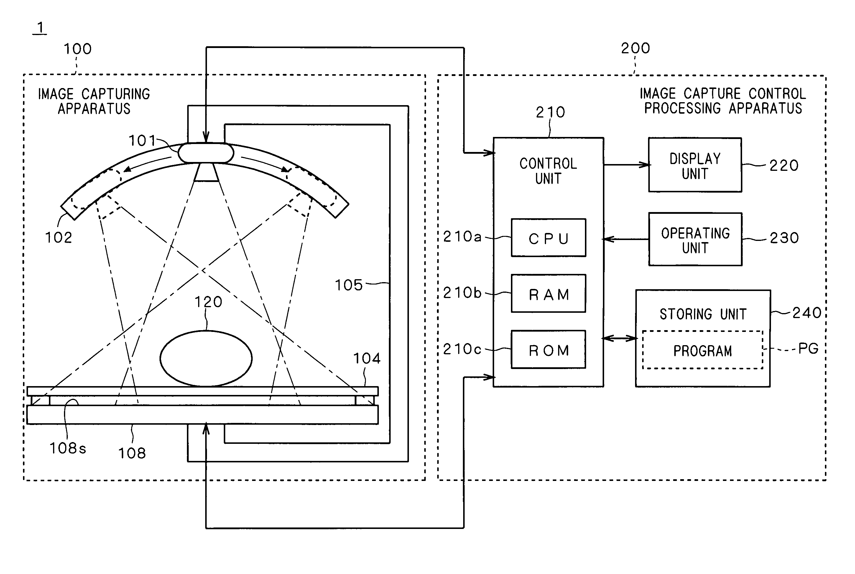
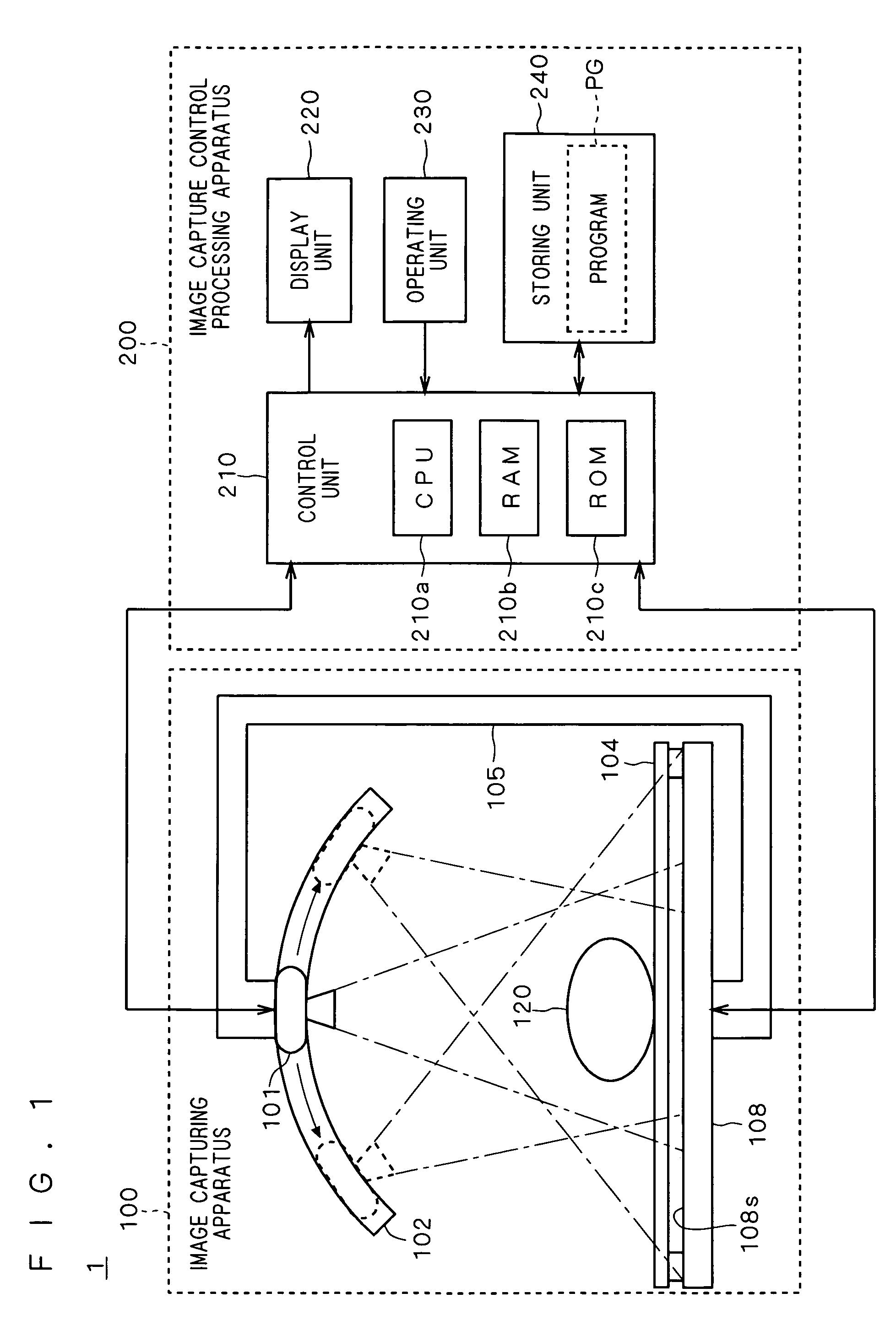
[0034]FIG. 1 is a diagram showing a schematic configuration of an image capturing system 1 of a first preferred embodiment of the present invention. The image capturing system 1 detects a distribution of radiation passing through a specimen 120 by using radiation (typically, X ray), and obtains a distribution of pixel values (transmission image), so that various information processes using the transmission image can be performed. That is, the image capturing system 1 functions as a system for capturing a transmission image (transmission image capturing system).

[0035]The image capturing system 1 includes an image capturing apparatus 100 and an image capture control processing apparatus 200. It is assumed that the specimen 120 as an object to image capturing is the body of a person to take a test. An oval in the diagram schematically expresses the body of the specimen.

[0036]The image capturing apparatus 100 has, mainly, a emitting gener...

second preferred embodiment

[0119]In the image capturing system 1 of the first preferred embodiment, the outer-edge shape of the radiation area is recognized from the transmission images. On the other hand, in an image capturing system 1A of a second preferred embodiment, an irradiation area on the detection surface 108s is illuminated by lighting and is photographed by a camera. The outer-edge shape of the radiation area is recognized from obtained photographed images.

[0120]The image capturing system 1A of the second preferred embodiment will be described below. The image capturing system 1A of the second preferred embodiment has a configuration similar to that of the image capturing system 1 of the first preferred embodiment except for the configuration of recognizing the outer-edge shape of the radiation area. Consequently, the same reference numerals are designated to the similar components and their description will not be repeated. Mainly, the different configuration will be described.

[0121]FIG. 13 is a ...


PUM


Abstract

The present invention proposes a technique capable of accurately grasping position and angle of a radiation generator at the time of image capturing. At the time of obtaining a plurality of transmission images by detecting radiation emitted from a emitting generator and passing through a specimen via a predetermined member (for example, a diaphragm) by a detector for a plurality of times while changing a relative position relation and a relative angle relation of the emitting generator to the detector, an outer-edge shape of a radiation area irradiated with the radiation on a detection surface of the detector from the emitting generator is recognized. On the basis of the outer-edge shape of the radiation area and an inner-edge shape of a predetermined member, the relative position relation and the relative angle relation of the emitting generator to the detector are obtained.

Description

[0001]This application is based on application No. 2007-178396 filed in Japan, the contents of which are hereby incorporated by reference.BACKGROUND OF THE INVENTION[0002]1. Field of the Invention[0003]The present invention relates to a transmission image capturing technique.[0004]2. Description of the Background Art[0005]In medical fields, transmission images of a human body are captured by using X ray or the like. By reading the transmission images, diagnosis is conducted.[0006]An X-ray diagnosing apparatus for so-called tomosynthesis is proposed, capable of observing a slice plane of a specimen at an arbitrary depth by synthesizing (reconstructing) a plurality of pieces of image data obtained by irradiating the specimen with X ray in different directions by image capturing using X ray.[0007]At the time of capturing a plurality of projection images to generate an image of a slice plane, the position and angle of a scan system such as a part that emits radiation (for example, an X-...

Claims


Application Information

Patent Timeline
Patent Type & Authority Patents(United States)
IPC IPC(8): H05G1/60A61B6/08G01D18/00
CPCA61B6/025G01N23/046G01N2223/612G01N2223/419G01N2223/316
Inventor FUJIWARA, KOICHITOYAMA, OSAMUNAGATSUKA, SUMIYA
Owner KONICA MINOLTA INC
Why Eureka
Try Eureka