Articulation apparatus for external fixation device

a technology of fixing device and articulation apparatus, which is applied in the direction of invalid friendly devices, rod connections, prostheses, etc., can solve the problems of difficult to hold all components in their proper relative orientation prior to or during final locking of the device, and create a challenge, so as to achieve low load, less weight, and high load

Active Publication Date: 2010-05-04
ZIMMER INC
View PDF25 Cites 93 Cited by
  • Summary
  • Abstract
  • Description
  • Claims
  • Application Information

AI Technical Summary

Benefits of technology

[0012]In accordance with one aspect of the present invention, the present invention aims to provide greater placement flexibility in a more compact construct than is presently available. It comprises the placement of fixation elements on either side of a fracture. These fixation elements are commonly referred to as pins, whereby one or more pins are screwed into a bone. One or more pins are located on either side of a fracture and connected to a bar via a clamp and / or a clamping system. The present invention relates to connecting pins with one or more bars in order to fixate a fracture. Such bars may also be connected to other bars or structures, if needed. In connecting pins to rods, it is advantageous to have mobility in a clamping system to allow for ease of placement and / or post placement manipulation.
[0013]One illustrative embodiment of the present invention comprises two (2) independent but connected clamp jaws, each clamp jaw being set in a clamp housing. Each clamp jaw comprises two (2) clamp jaw halves. The clamp jaw halves are shaped such that a clamp jaw is able to open and close around a bar or pin. In this embodiment of the present invention, the clamp jaw is able to clamp around a bar, while simultaneously, a connected corresponding clamp jaw is able to pivot about an axis normal to the axis of a pin or bar that is being clamped. Clamp jaw halves may be circular in shape to surround a pin or bar with a circular cross section. The clamp jaw halves may also be shaped to correspond to the cross section of the shape of the pin or bar being clamped. In another embodiment of the present invention, the clamp jaws may also be connected such that the clamp jaws also allows a bar or pin to rotate and approximately and / or equal to 20 degrees while clamped to allow for greater range and ease of positioning.
[0015]In the illustrative embodiment of the present invention, two (2) clamp housings are connected to each other by a collar. The collar has an interior diameter which comprises both a right hand female thread and left hand female thread. Each clamp housing also comprises a corresponding right male thread and a left male thread which attach the clamp housings to the collar. The clamp housings may be keyed to each other such that the clamp housings are limited in rotation to 180 degrees relative to each other. This prevents the clamp housings from having an unequal thread engagement in the collar and limits unnecessary range of motion.
[0018]Advantages of the present invention comprise the following: the present invention allows for one-handed application; includes one lock per joint; allows for greater degrees of freedom in mounting; allows for gross manipulation; accommodates multiple indications; comprises few components; and requires minimal training.

Problems solved by technology

A drawback of such a device is that the articulation elements require being mounted on the fixation bars or the pins via their ends in advance of attachment.
Until the clamping mechanism in such device is locked, the components are not held firmly and can move with respect to one another, making it difficult to hold all components in their proper relative orientation prior to or during final locking of the device.
In complex fractures there is often a need to place many pins, either because there are many fragments, or due to the poor quality of the bone and / or the nature of the fracture.
Many pins, many of which will present themselves in different attitudes and inclinations, create a challenge when it comes time to connect them to the external structure.
Unless the beam or the foundation is of sufficient flexibility it is impossible to share the load evenly across all of the multiple supports.
This added spherical joint does however come at some expense, namely the pin to bar centerline distance must be increased, which makes for a bulkier construct while at the same time increasing the moment loading on the joints themselves.

Method used


Image

  • Articulation apparatus for external fixation device
  • Articulation apparatus for external fixation device
  • Articulation apparatus for external fixation device

Examples


Embodiment Construction

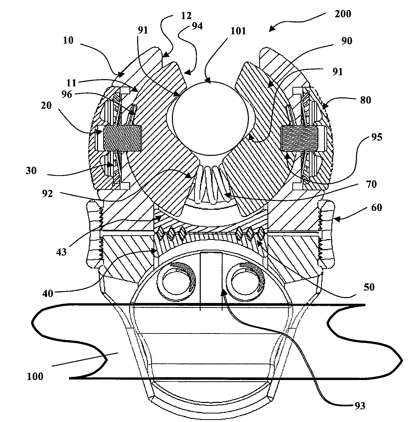
[0029]The external fixation system of the present invention includes an articulation element employed in the fixation of cylindrical components, namely bone pins and bar systems. Its structure and functional details will be discussed in detail below in the context of an illustrative embodiment and with reference to the figures provided.

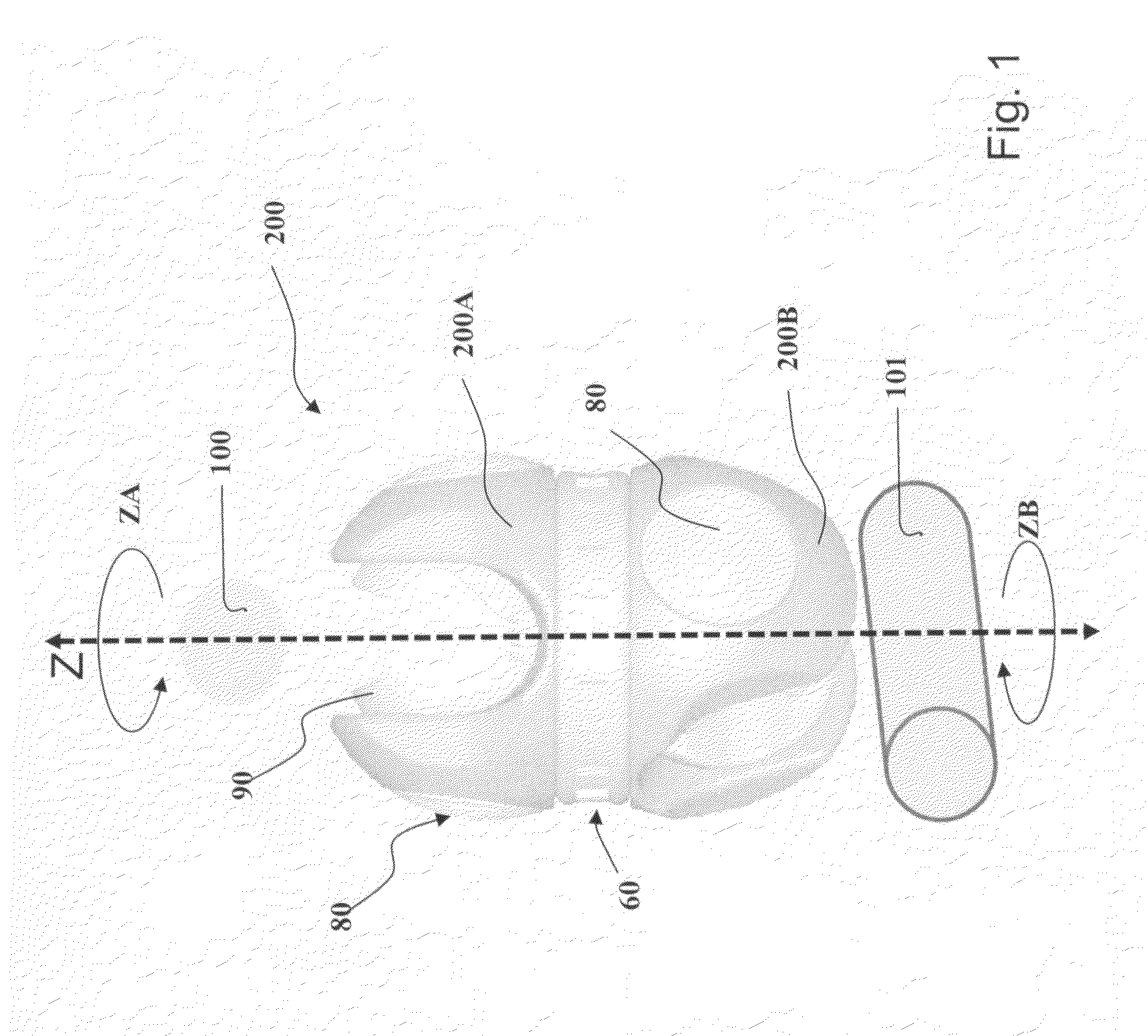
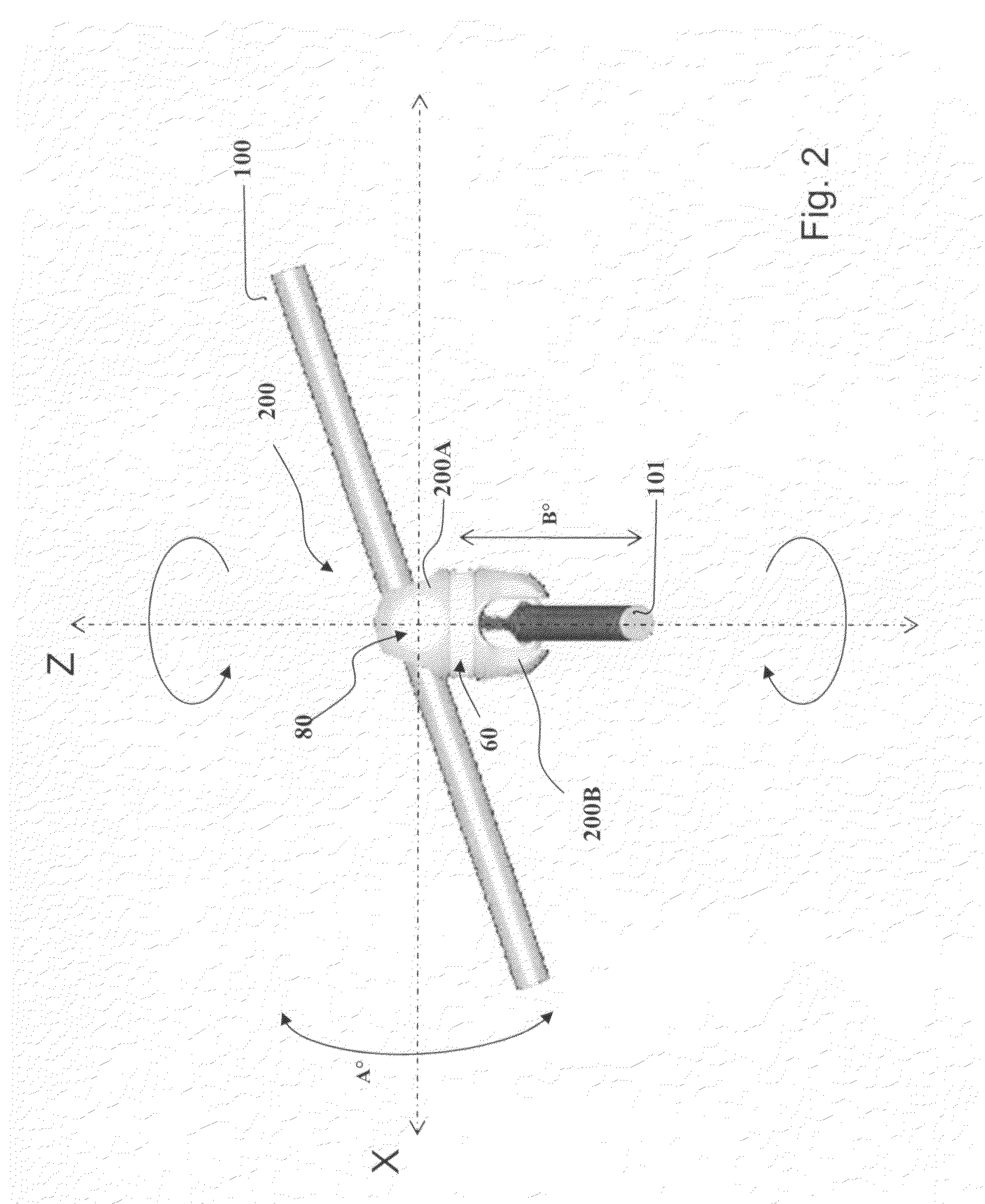
[0030]FIGS. 1 and 2 show isometric views of an articulation element 200 according to an illustrative embodiment of the present invention.

[0031]The articulation element 200 consists of a pair of back-to-back spherical clamping mechanisms 200A and 200B that act to apply clamping pressure to cylindrical bars and / or pins shown conceptually as 100 and 101. The clamping mechanisms themselves consist of a pair of spherical jaw elements 90 within each of the spherical clamping mechanisms. Release buttons 80 allow the preloaded jaw elements 90 to relax to receive or release a rod or pin 100. Each mechanism 200A and 200B freely rotates about axis Z (i.e., in ei...


PUM


Abstract

An articulation element consisting of a plurality of adjustable jaw pairs for the purpose of fixating the relative position of coupled bars and / or bone pins of an external bone fixator. Each of the adjustable jaws consists of a pair of hemispherical jaw elements contained within a spherical housing. A passage is eccentrically arranged through the jaw elements to accept the pin or bar. The jaw elements have interposed between them a spring element that serves to bias the jaw elements in the closed position. Pins serve to provisionally lock the jaw elements in the closed position. Spring loaded buttons act to release the pins thereby allowing the jaw elements to open accepting the pin or bar. The jaws are attached in a back to back fashion through the use of a threaded collar which acts as a turnbuckle pulling the jaws together when tightened.

Description

[0001]This application claims the benefit of U.S. Provisional Application No. 60 / 775,565, filed Feb. 22, 2006, which is incorporated herein by reference in its entirety.FIELD OF THE INVENTION[0002]This innovation relates to an articulation element employed in the fixation of cylindrical components, namely bone pins and bar systems, utilized in the field of external fixation.BACKGROUND OF THE INVENTION[0003]External fixation devices typically include external frames which are used in conjunction with bone pins which are surgically placed into the bone fragments to be repaired or immobilized to promote healing. Such external fixation systems allow for particular placement of the bone pins that hold the bone fragment into which they are inserted, as there are often characteristics in the affected area that require delicate placement of pins such as proximity to nerves or arteries, or around joints.[0004]The field of external fixation varies widely comprising many different types of app...

Claims


Application Information

Patent Timeline
Patent Type & Authority Patents(United States)
IPC IPC(8): A61B17/00
CPCA61B17/645A61B17/6466F16B2/10A61B17/60Y10T403/32Y10T403/7105F16B7/0493
Inventor MULLANEY, MICHAEL W.
Owner ZIMMER INC
Why Eureka
Try Eureka