Spinal plug for a minimally invasive facet joint fusion system

a facet joint and spine technology, applied in the field of minimally invasive spine surgery, can solve the problems of joint dysfunction, non-surgical symptomatic treatment, disease or consequences of injury, and progressively worsening disease or consequences, and achieve the effect of providing additional structural stability to the join

Inactive Publication Date: 2010-05-04
MINSURG INT INC
View PDF223 Cites 218 Cited by
  • Summary
  • Abstract
  • Description
  • Claims
  • Application Information

AI Technical Summary

Benefits of technology

[0009]The use of pre-shaped, harvested or synthetic bone as a structural fixation for facet joint fusion offers three distinct advantages over pedicle or compression screws, which are presently used in facet fusion procedures; i.e., (1) using bone instead of metal allowing for natural bone ingrowth and a stronger, permanent fusion; and (2) the natural or synthetic graft cannot work its way loose over time, a concern with screw type fixation.
[0010]The grafts and system are specifically designed for use in a minimum invasive or an arthroscopic type portal for stand-alone procedures and provide a stronger, unique and superior fusion when used as an adjunct to instrumented vertebral fusion by greatly reducing risk of facet joint pain resulting from persistent facet joint motion.
[0011]The instrumentation, grafts and method are specifically designed for use in an arthroscopic type portal for stand-alone procedures and provides a stronger, unique and superior fusion when used as an adjunct to instrumented vertebral fusion by eliminating the risk of collateral post-operative facet joint pain resulting from additional stress placed on facet joints by the instrumentation itself.
[0017]The impactor or tamp includes any number of components capable of pushing and compressing the bone plug into the bone tunnels. A suture or metallic overlay also can be applied to provide additional structural stability to the joint during graft incorporation.

Problems solved by technology

Present surgical solutions available for the millions of people with facet joint dysfunctions are complex, invasive, pedicle screw based high-risk operations with prolonged recovery times, from 6 to 24 months, and uncertain outcomes.
High risk equates to frequent litigation, which forces non-surgical symptomatic treatment while the disease or consequences of injury progressively worsen.

Method used


Image

  • Spinal plug for a minimally invasive facet joint fusion system
  • Spinal plug for a minimally invasive facet joint fusion system
  • Spinal plug for a minimally invasive facet joint fusion system

Examples


Embodiment Construction

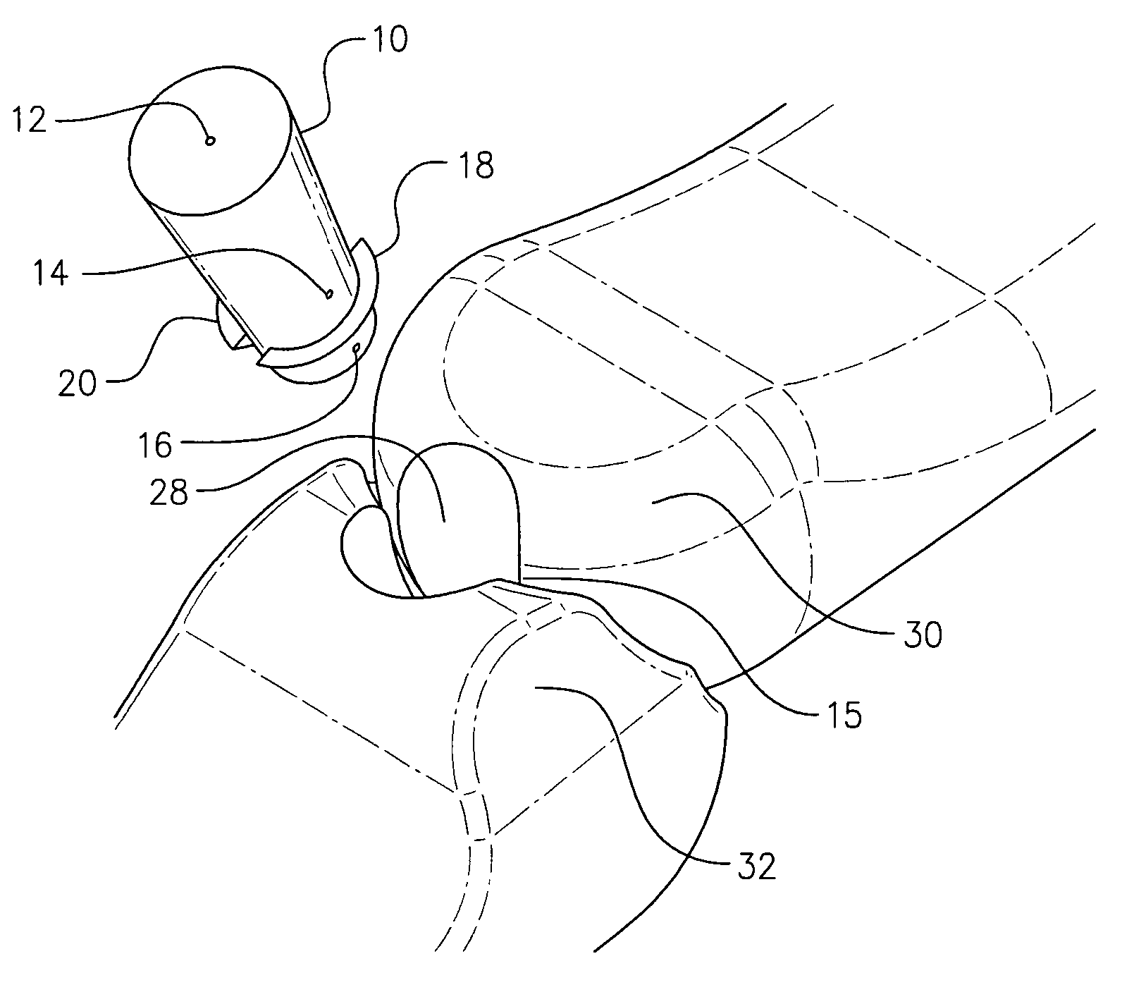
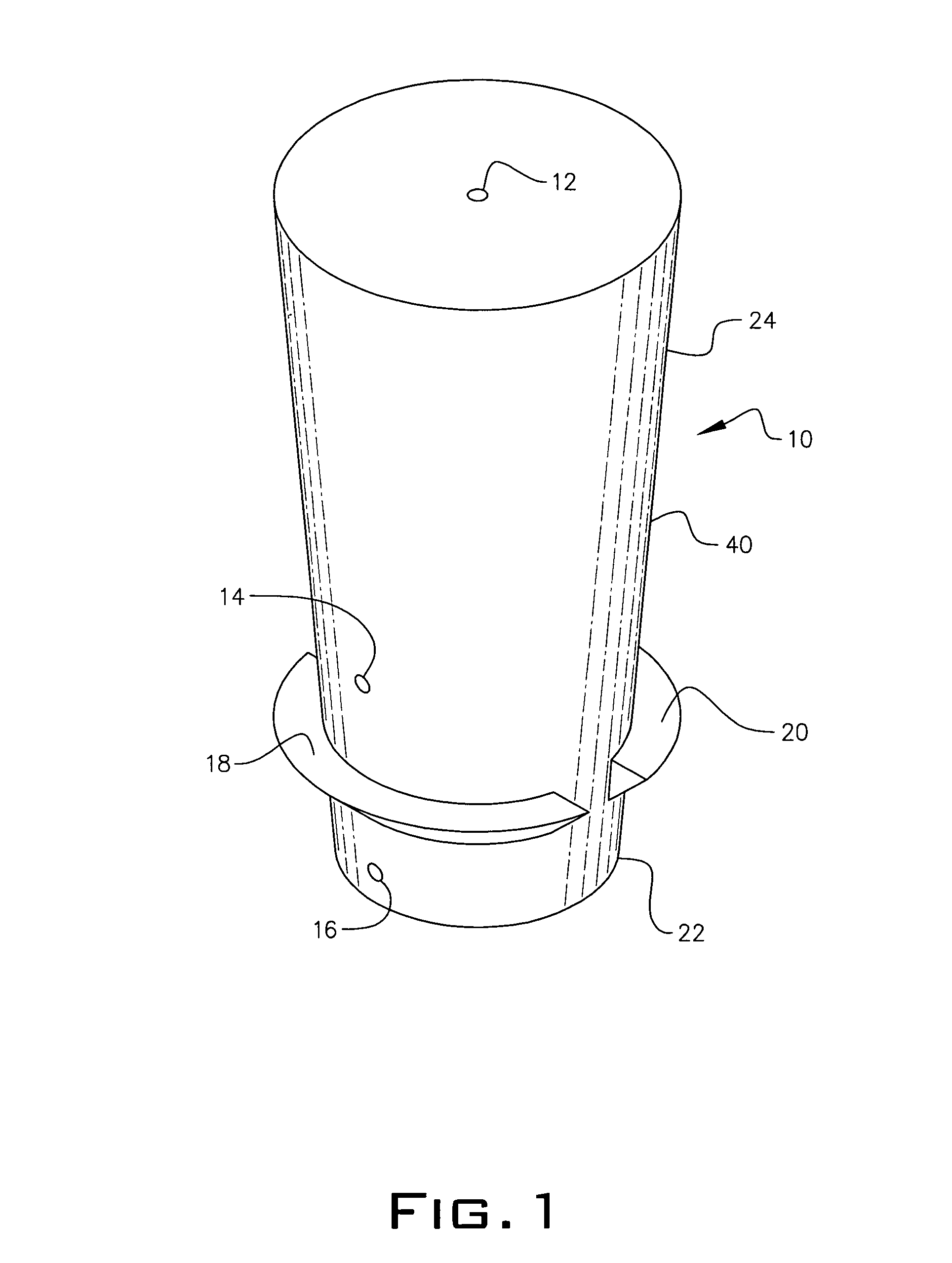
[0031]Referring to FIG. 1, the bone plug of this invention is an inverted frustum shaped device 10 having a vertical central channel 12 for insertion of a synthetic or biologic material to assist in fusing the bone plug 10 in place in a spinal joint 15. The bone plug 10 has multiple side parts 14 and 16 for excretion of the synthetic or biologic material from the central channel 12. A pair of opposed flanges 18 and 20 on the same plane partially circumvent the bone plug 10 near bottom end 22 having a smaller diameter than the top end 24.

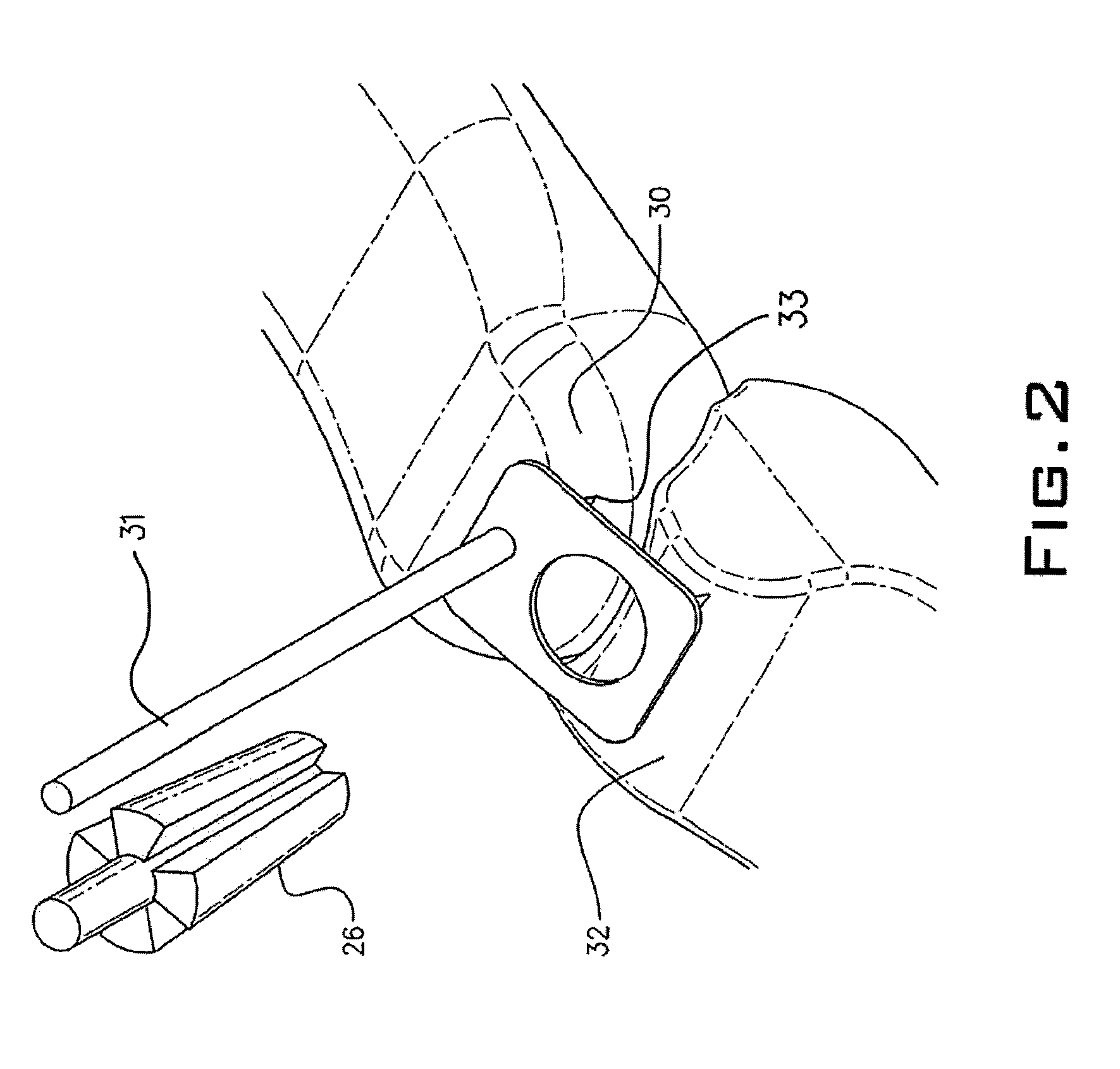
[0032]In order to fuse a spinal facet joint, a tapered drill 26, shown in FIG. 2, is employed to prepare a hole 28 shown in FIG. 3 between two bones 30 and 32. A drill guide 31 may be used to guide the tapered drill 26 to prepare the hole 28 in the correct location. Drill guide 31 may be secured to the facet joint by teeth 33 to prevent displacement during hole preparation. As seen in FIG. 4, an application tube 34 is inserted in channel 12 to permit...


PUM


Abstract

A frustum shaped body has an aperture in a top surface and a pair of first and second opposed apertures in a side surface, first and second horizontal internal channels connect both the first and second opposed apertures. A vertical channel from the top aperture connects with the first and second channels. After the body is inserted into a hole in a facet joint, compatible synthetic or biologic material is inserted into the vertical channel until the material exits from the first and second apertures in the side surface. At least one pair of flanges on a portion of an exterior side surface of the body acts as a detent to hold the body in place within the facet joint hole.

Description

PRIOR APPLICATIONS[0001]This application is a continuation-in-part from application Ser. No. 10 / 992,720, filed Nov. 22, 2004, which is expressly incorporated herein by reference.BACKGROUND OF THE INVENTION[0002]1. Field of the Invention[0003]The present invention relates generally to minimally invasive spine surgery and, more particularly, to using an arthroscopic type portal or open facet joint fusion surgical instrumentation for insertion of either pre-made, pre-shaped synthetic cortical bone or harvested and compacted iliac crest grafts, autologous or cadaveric allografts. The graft and fusion system is limited to the forty-eight facet joints located on the spine, C1-C2 through L5-S1.[0004]2. Description of the Prior Art[0005]In the United States alone, about 10% of the entire population will suffer from back pain sometime in the next twelve months. More people will contract back pain in the next year than any other injury or disease except the common cold and flu. About one-thir...

Claims


Application Information

Patent Timeline
Patent Type & Authority Patents(United States)
IPC IPC(8): A61B17/70
CPCA61B17/1604A61B17/1671A61B17/7064A61L27/3608A61B2019/304A61F2/28A61L2430/02A61F2/4455A61F2002/30785A61F2002/30881A61F2310/00359A61F2/4405A61B2090/034A61F2/44
Inventor PETERSEN, DAVID A.
Owner MINSURG INT INC
Why Eureka
Try Eureka