
Radiation detector

a detector and vapor proof technology, applied in the field of radiation detectors, can solve the problems of reducing the service life affecting the operation and the end portion of the vapor proof protection film is liable to be rolled up, so as to achieve the effect of suppressing the protection layer

Active Publication Date: 2010-05-04
FUJIFILM CORP
View PDF5 Cites 3 Cited by
  • Summary
  • Abstract
  • Description
  • Claims
  • Application Information

AI Technical Summary

Benefits of technology

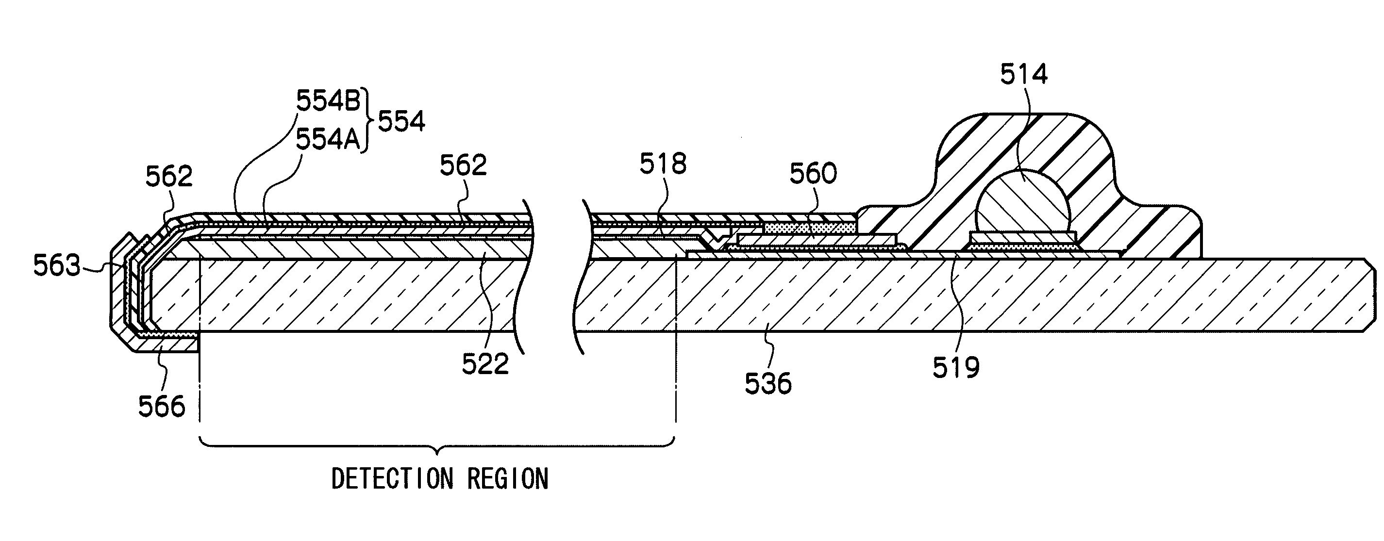
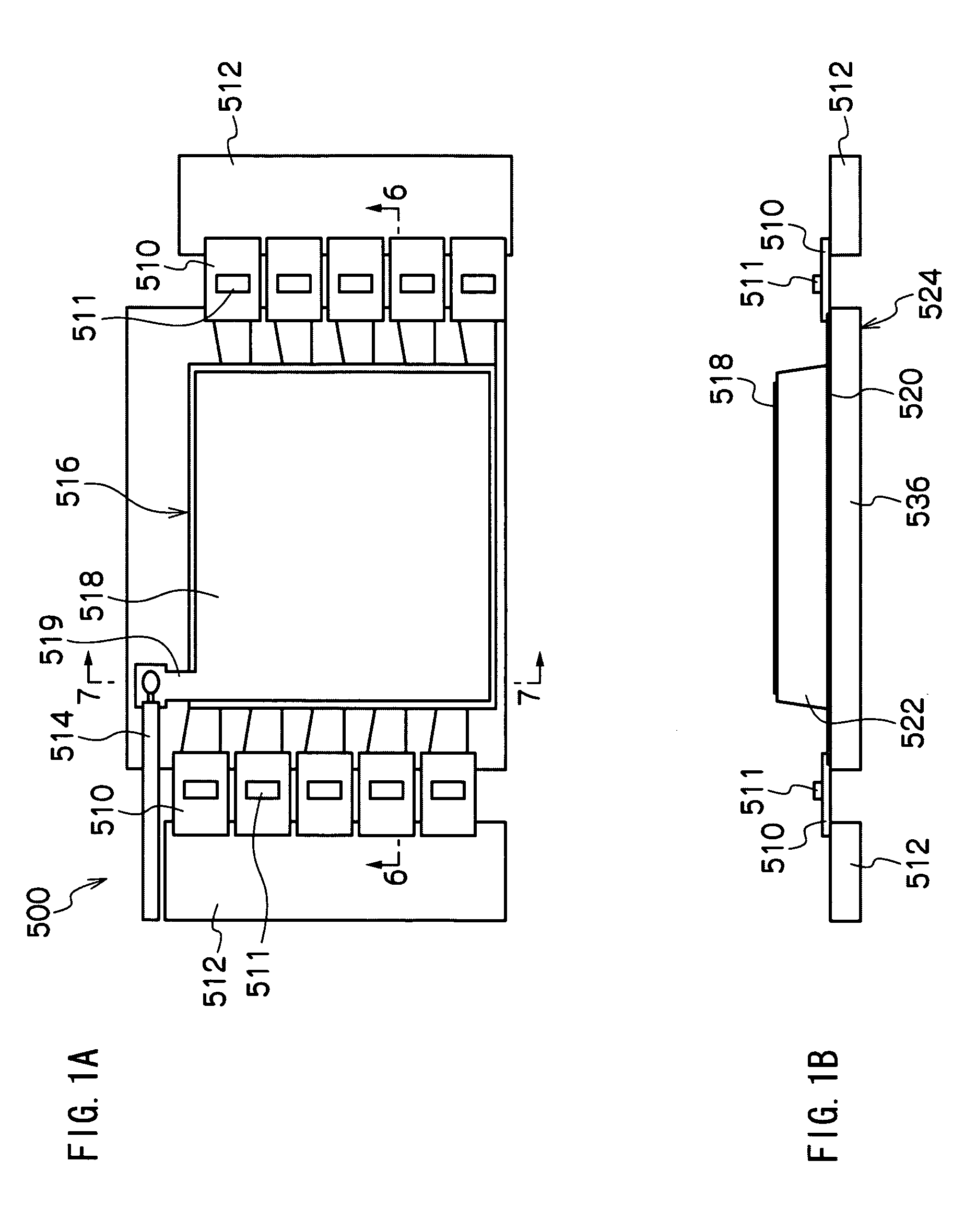
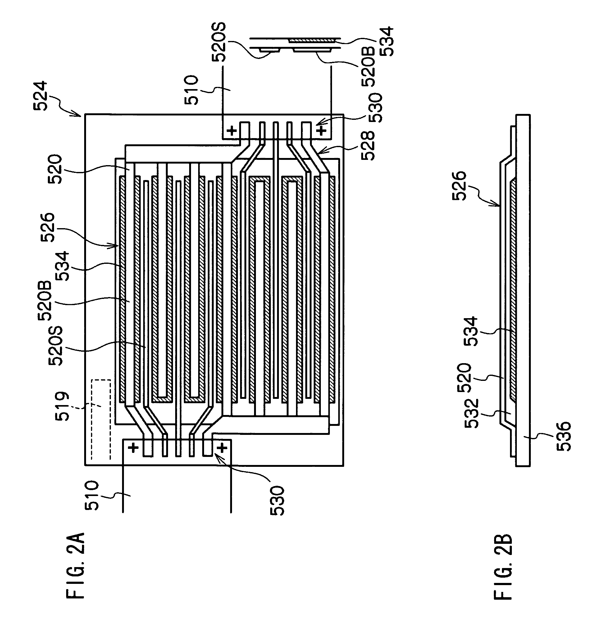
The present invention aims to prevent the breakage of a protection layer on the end surface of a substrate in a radiation detector. The invention includes a substrate, a lower electrode, a radiation detecting layer, an upper electrode, a protection layer, and a reinforcement member. The protection layer covers the upper electrode and its end portion extends to the end surface of the substrate. The reinforcement member covers the end portion of the protection layer. This prevents the end portion of the protection layer from being rolled up and peeled off, which could lead to damage to the substrate.

Problems solved by technology

A vapor proof effect may not be obtained in a case that a vapor proof protection film is bonded on the top surface of the substrate where the distance between a phosphor layer and the side surface at one side of the substrate is short.
However, when the vapor proof protection film is deteriorated with time or when the vapor proof protection film is touched from the outside, the end portion of the vapor proof protection film is liable to be rolled up.
When the end portion of the vapor proof protection film is rolled up, there is a possibility that the vapor proof protection film is peeled and broken.

Method used


Image

  • Radiation detector
  • Radiation detector
  • Radiation detector

Examples


Embodiment Construction

[0026]An exemplary embodiment of a radiation detector according to the present invention will be explained below based on drawings.

[0027]The radiation detector according to the exemplary embodiment is used in an radiographic apparatus, has an electrostatic recording unit including a photoconductive layer which exhibits conductivity when it is radiated with radiation, records image information when it is radiated with radiation carrying the image information, and outputs an image signal showing the recorded image information.

[0028]The radiation detector includes a radiation detector using a so-called optical reading system using a semiconductor material for generating charges in response to radiation of light, a radiation detector using an electric reading system which accumulates the charges generated by irradiation and detects the accumulated charges by turning on and off the pixels of an electric switch such as thin film transistor (TFT), charge coupled device (CCD), or complement...


PUM


Abstract

A radiation detector includes a substrate, a lower electrode disposed on the substrate, a radiation detecting layer formed on the upper surface of the lower electrode, an upper electrode formed on the upper surface of the radiation detecting layer, a protection layer which is formed on the upper electrode, whose end portion extends to an end surface of the substrate and which covers the upper electrode, and a reinforcement member which is formed from the lower surface of the substrate to the surface of the protection layer and which covers the end portion of the protection layer.

Description

CROSS-REFERENCE TO RELATED APPLICATION[0001]This application claims priority under 35 USC 119 from Japanese Patent Application, No. 2007-196525, the disclosure of which is incorporated by reference herein.BACKGROUND OF THE INVENTION[0002]1. Technical Field[0003]The present invention relates to a radiation detector used in a medical radiographic apparatus.[0004]2. Related Art[0005]There are known, as a radiation detector, an indirect conversion type electromagnetic radiation detector by which, after radiation such as X-rays and the like is converted into light first, the converted light is further converted into an electric signal by photoelectric conversion. And a direct conversion type electromagnetic radiation detector by which incident radiation is converted into an electric signal immediately by a charge conversion layer. Further, the radiation detector disclosed in Japanese Patent Application Laid-Open (JP-A) No. 2006-58171 is known as the electromagnetic radiation detector usi...

Claims


Application Information

Patent Timeline
Patent Type & Authority Patents(United States)
IPC IPC(8): G01T1/24A61B6/00H01L27/14H01L27/144H01L31/09H04N25/00
CPCG01T1/2928G01T1/246G01T1/244
Inventor SAKAMOTO, YOSHIAKIYOSHIDA, FUTOSHISHOJI, TAKASHIASANO, TAKESHI
Owner FUJIFILM CORP
Learn More