Method for producing plasma display panel with a bright display and a low operating voltage

a plasma display and operating voltage technology, applied in the manufacture of electric discharge tubes/lamps, electrodes, electromechanical systems, etc., can solve the problems of difficult to decrease the operating voltage, inability to produce plasma display panels, etc., to reduce the starting voltage of electric discharge panels, reduce operating voltage, and suppress protective layers and impurities

Inactive Publication Date: 2012-04-24
PANASONIC CORP
View PDF12 Cites 2 Cited by
  • Summary
  • Abstract
  • Description
  • Claims
  • Application Information

AI Technical Summary

Benefits of technology

[0015]For one thing, the method of the present invention is characterized in that the protective layer of the front panel is heated to a temperature in a range from 1600° C. to 3600° C. at a certain point in time after the preparation of the front panel and before the sealing of the front and rear panels (see FIG. 1), such temperature being a very high temperature which is not employed in the conventional PDP producing process. Such heating of the protective layer makes it possible to remove impurities (e.g. H2O and CO2) from the protective layer. Furthermore, due to the heating of the protective layer, the protective layer after being heated is suppressed from reacting with the impurities (such as H2O and CO2).
[0024]The method of the present invention enables it not only to remove impurities of the protective layer (e.g. H2O and CO2) therefrom, but also thereafter to suppress the protective layer and the impurity (e.g. H2O and CO2) from reacting with each other. Therefore, in accordance with the method of the present invention, a desired component of the protective layer (e.g. oxide of alkaline earth element) can be positively used, such component tending to absorb or adsorb impurities, but being favorable in terms of electric discharge characteristic and lower operating voltage.
[0025]More specifically, the method of the present invention enables it to use at least one kind of metal oxide selected from among magnesium oxide, calcium oxide, strontium oxide and barium oxide as the component of the protective layer. In particular, it is possible to use the metal oxide consisting of at least two oxides selected from among magnesium oxide, calcium oxide, strontium oxide and barium oxide, said metal oxide having a peak diffraction angle between the minimum diffraction angle and the maximum diffraction angle which are selected among the diffraction angles given by respective ones of said at least two oxides constituting the metal oxide with respect to a specific orientation plane in X-ray diffraction analysis. Use of such component in the protective layer can lower the electric discharge starting voltage of the panel, and decrease the delay of the electric discharge, thereby providing a particularly significant effect in terms of a stable electric discharge.
[0026]The metal oxides described above is highly reactive with impurity gases such as water gas and carbon dioxide gas. In general, the protective layer thus tends to undergo a deterioration of discharge characteristic through the reaction with water and carbon dioxide. However, in this regard, according to the present invention, the impurities (i.e. H2O and CO2) of the protective layer can be removed from the protective layer, and thereafter the protective layer can be suppressed from reacting with the impurities (i.e. H2O and CO2 gas). Therefore, such metal oxides can be positively used as the component of the protective layer (Namely, the use of the metal oxide as a component of the protective layer is effectively promoted).
[0027]In the PDP obtained by the present invention, the electric discharge starting voltage can be lowered due to the improved secondary electron emission characteristic of the protective layer, and also a delay of the electric discharge can be decreased, which leads to an achievement of a stability of the electric discharge. In other words, in the PDP produced by the method of the present invention, the lowering of the electric discharge starting voltage can be achieved even when a partial pressure of Xe gas is increased in order to improve the brightness of the PDP. Accordingly, the present invention can provides a plasma display panel with a higher brightness of picture display and a lower voltage driving.

Problems solved by technology

However, the oxides of alkaline earth metals have high hygroscopic property, and thus the protective layer made of such oxides tends to absorb the moisture of the atmosphere, and thereby the oxides of the protective layer turn into hydroxide.
This results in the instability of the electric discharge.
Also the oxides of these alkaline earth metals have tendency to turn into carbonated matter, making it difficult to decrease the operating voltage.

Method used


Image

  • Method for producing plasma display panel with a bright display and a low operating voltage
  • Method for producing plasma display panel with a bright display and a low operating voltage
  • Method for producing plasma display panel with a bright display and a low operating voltage

Examples


examples

Test to Evaluate Gas Desorption Characteristic

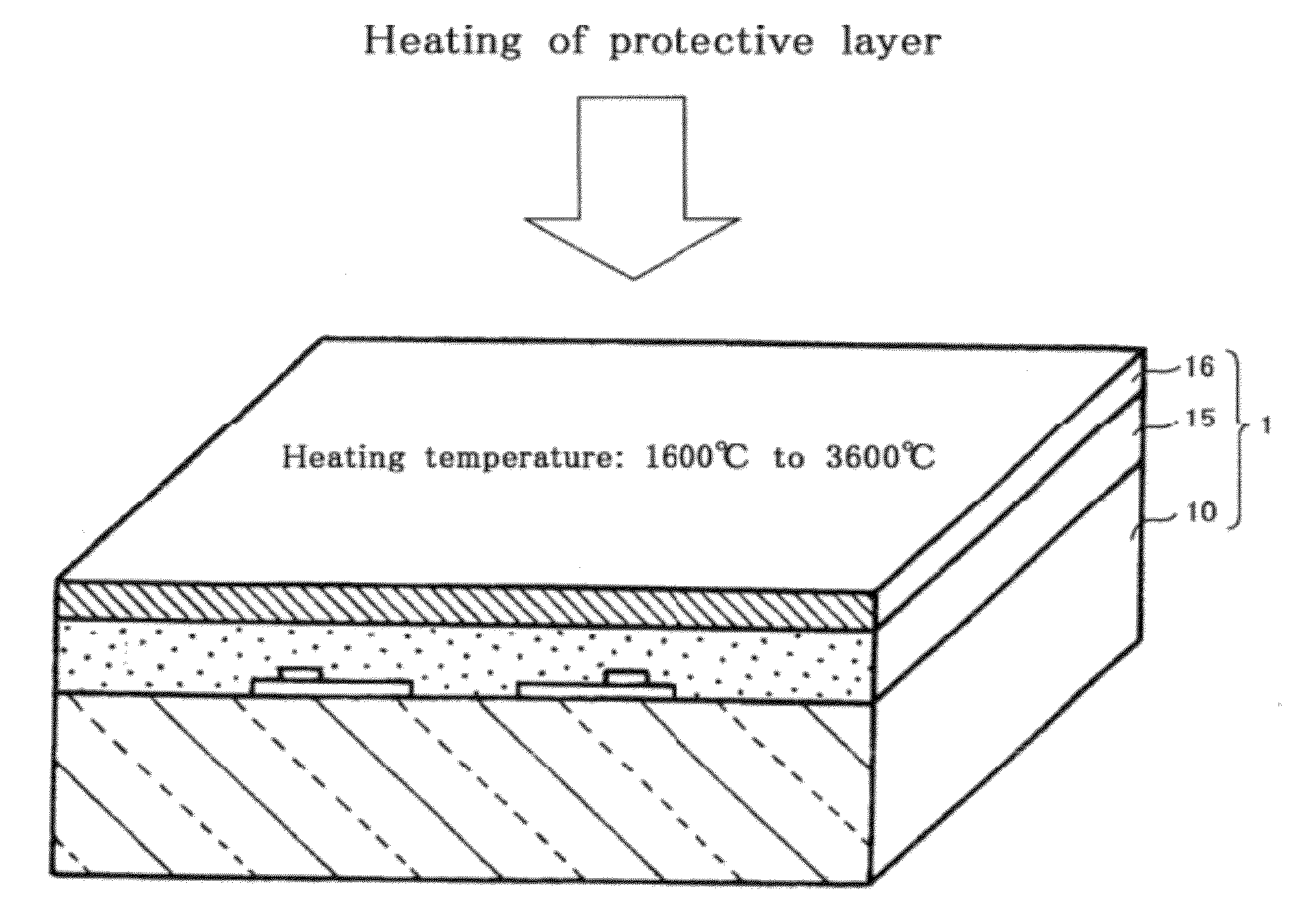
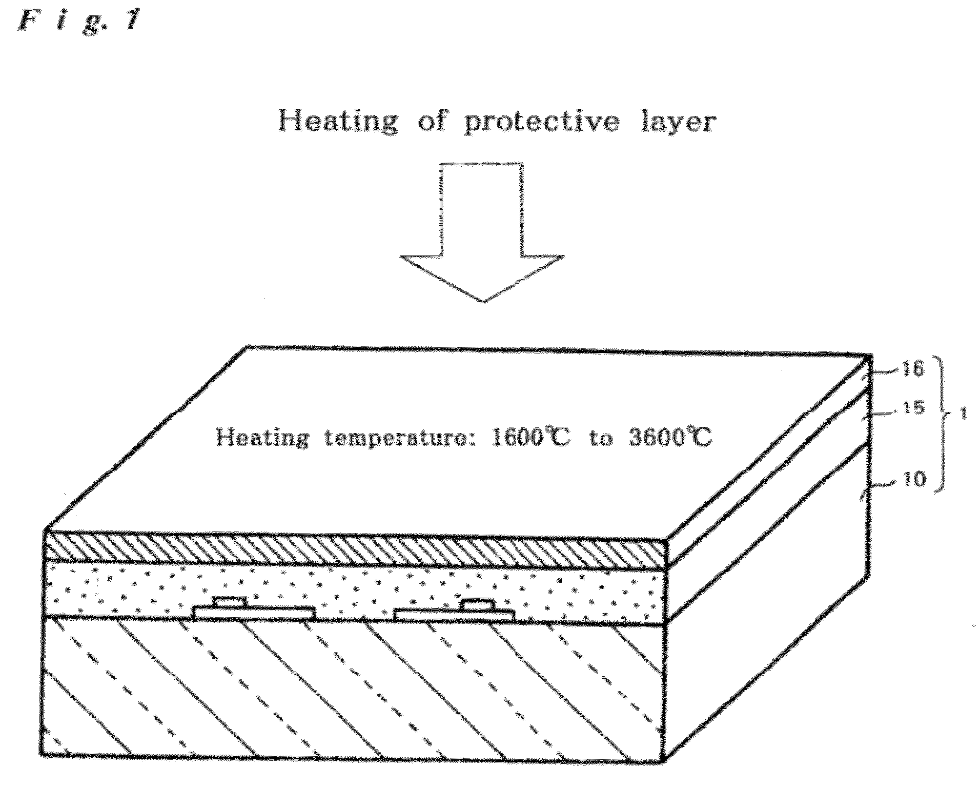
[0128]Test was conducted to study the dependency of a gas desorption characteristic on the heating temperature of the protective layer. For this test, the front panel with the following specifications was used:[0129]Component of the protective layer: Metal oxides comprising MgO and CaO[0130]Thickness of protective layer: 0.8 μm[0131]Component of dielectric layer: Low-melting point glass[0132]Thickness of dielectric layer: 40 μm[0133]Thickness of display electrode: 15 μm[0134]Thickness / component of bus electrode: 6 μm / Ag[0135]Thickness / component of transparent electrode: 100 nm / ITO[0136]Substrate A: 1.8 mm-thick soda lime glass manufactured by Nippon Electric Glass Co., Ltd.

[0137]The protective layer of the above front panel was subjected to a heat treatment by scanning a thermal plasma torch under the following conditions (heating temperature of protective layer: about 2000° C.)[0138]Distance (gap) between distal end of the nozzle of the...


PUM

PropertyMeasurementUnit
temperatureaaaaaaaaaa
velocityaaaaaaaaaa

Abstract

A method for producing a plasma display panel, the method including preparing a front panel and a rear panel, the front panel being a panel wherein a first electrode, a first dielectric layer and a protective layer are formed on a first substrate, and the rear panel being a panel wherein a second electrode, a second dielectric layer, a partition wall and a phosphor layer are formed on a second substrate; and opposing the front and rear panels with each other, and sealing the front and rear panels along their peripheries by a sealing material wherein the protective layer is heated to a temperature ranging from 1600° C. to 3600° C. before the sealing of the front and rear panels.

Description

FIELD OF THE INVENTION[0001]The present invention relates to a method for producing a plasma display panel which can be used for image display of televisions and computers.BACKGROUND OF THE INVENTION[0002]A plasma display panel (hereinafter also referred to as “PDP”) has the capabilities of high definition reproduction of pictures and a larger screen, and thus has been commercialized as 100-inch class television sets. In recent years, it has been attempted to apply the PDP to high definition television sets with twice or more scan lines as those of the conventional NTSC TV format. Furthermore, there have been increasing requirements for the PDP to have decreased power consumption for addressing the energy issue and to have lead-free material for meeting environmental requirements.[0003]The PDP is basically composed of a front panel and a rear panel. The front panel is disposed at the front such that it faces the viewer. Such front panel is generally provided with a glass substrate, ...

Claims


Application Information

Patent Timeline
Patent Type & Authority Patents(United States)
IPC IPC(8): H01J9/00H01J9/02H01J11/12H01J11/22H01J11/24H01J11/26H01J11/34H01J11/40
CPCH01J9/02H01J11/12H01J11/40
Inventor OKUMURA, TOMOHIRO
Owner PANASONIC CORP
Why Eureka
Try Eureka