Linear wind-powered electric generator

a technology of electric generators and wind turbines, applied in the direction of electric generator control, machines/engines, mechanical equipment, etc., can solve the problems of low efficiency of blades with one axis of rotation, and high noise of blade tip, etc., to achieve the best aerodynamic performance, improve aerodynamic performance, and enhance the degree of energy extraction

Inactive Publication Date: 2010-05-04
NOSTRUM ENERGY PTE LTD
View PDF13 Cites 25 Cited by
  • Summary
  • Abstract
  • Description
  • Claims
  • Application Information

AI Technical Summary

Benefits of technology

[0015]Basically, all the aerodynamic disadvantage of lengthy blades rotating around a single center axis can be mitigated if a blade of constant or variable cross section is moved across the wind in a straight line, and by using the component of the lift force to move the blade and to thereby extract energy. However, for a continuous operation, the blade element must return back to its starting point, consequently, there is a need in the technology to develop a highly efficient, simple, cost-effectively competitive linear wind power-generating installation that is more specifically adapted for ultra-low Class 2 wind density sites, wherein the invention provides a significant advance in the field of wind power energy, designed to be predicated on a simple linear track-based arrangement.
[0023]According to the present invention, the blades or wings, while operating as lift elements, move in a substantially straight path across the freely-streaming wind, resulting in a significantly improved aerodynamic performance, and hence, in an enhanced degree of energy extraction from the wind in comparison with the prior art. The blades or wings must move several times (typically 3 to 6 times) faster than the speed of the wind to achieve the best aerodynamic performance, inasmuch as the rotating parts of the installations are subjected to inertial loads while turning around corners along the paths of travel. According to the present invention, such an operation is feasible in a practical mode at the very low or ultra-low wind speeds of Class 2.

Problems solved by technology

The blade design is normally optimized to facilitate obtaining the best aerodynamic and structural performance, but the fact remains that blade elements very close to the center axis of rotation are aerodynamically ineffective, whereas those close to or at the blade tip produce considerable levels of noise due to high speeds and vortex shedding.
The larger the unit power for a given wind class, the larger is the diameter, the taller is the tower, and more complex are the therewith associated structural problems.
The designs with one axis of rotation are, however, very compact in configuration, especially the HAWT with just two or three blades.

Method used


Image

  • Linear wind-powered electric generator
  • Linear wind-powered electric generator
  • Linear wind-powered electric generator

Examples


Embodiment Construction

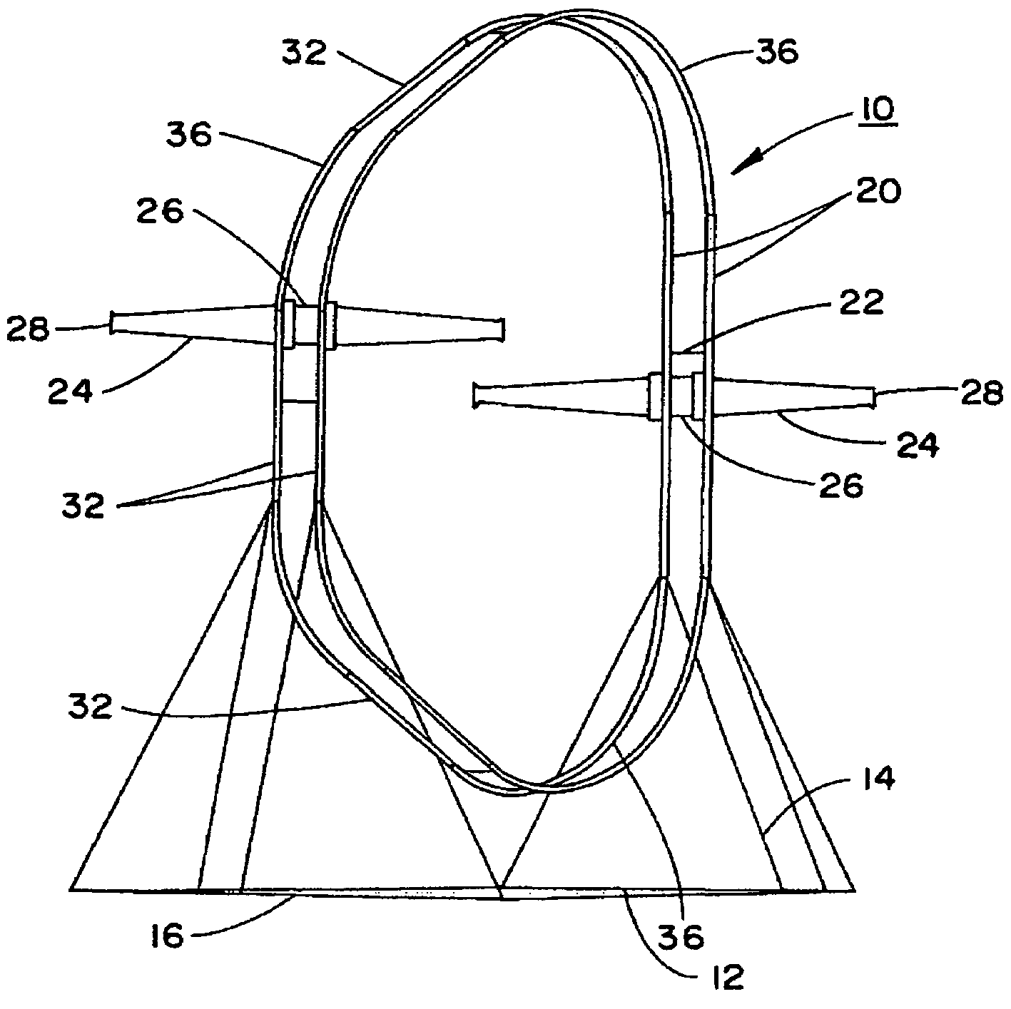
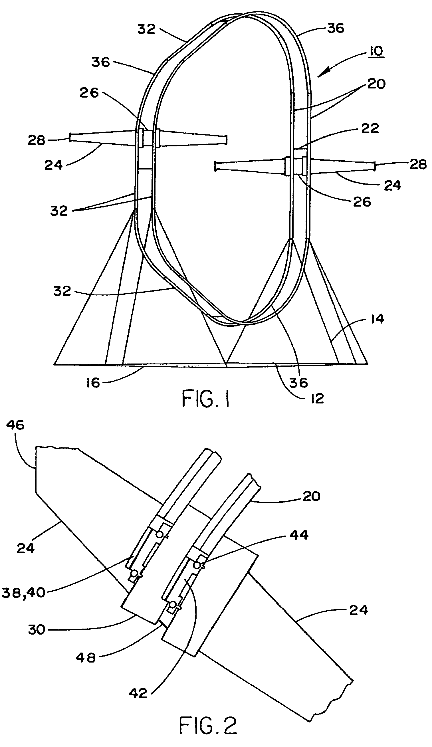
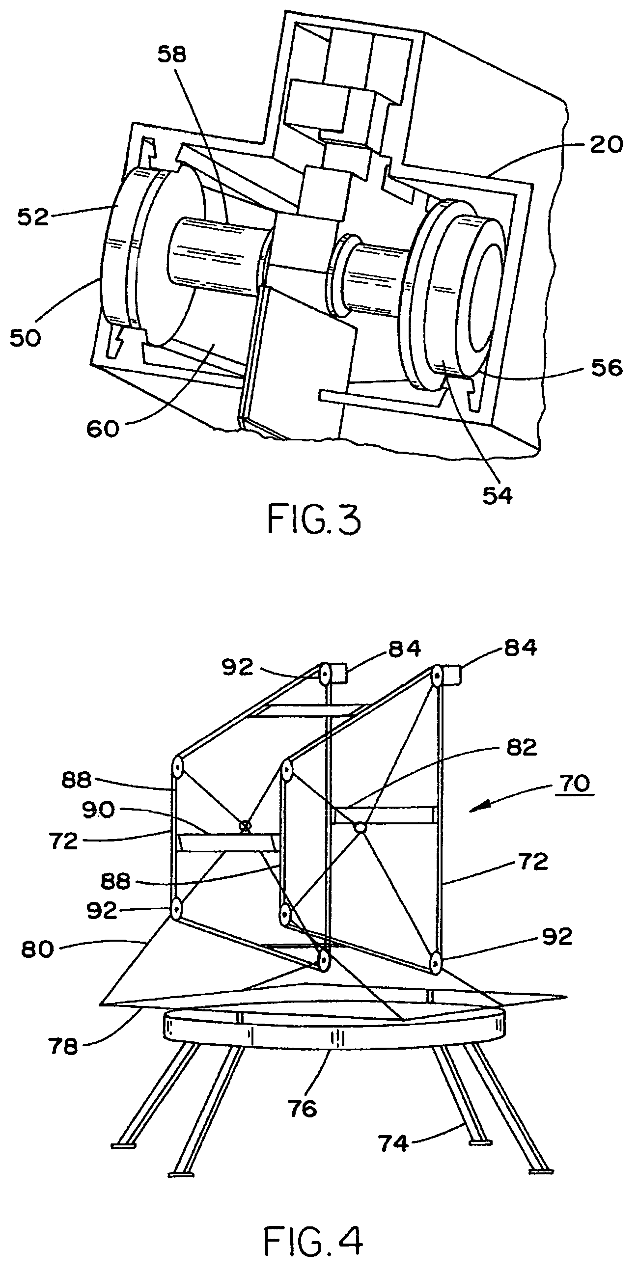
[0041]Basically, in general terms, the novel linear wind powered electric generator (LWPEG) according to the present invention is aerodynamically optimally designed for very low and ultra-low wind velocities, such as Class 2 wind intensity sites. The linear wind powered electric generators (LWPEG) as illustrated in the various embodiments of the present invention each comprise a suitable number of blades or wings of predetermined chord, airfoil section, span, planform shape, internal load bearing structure and tip wing-plate dimensions, and are made to travel along preferably non-circular orbits of various configurations, such as oval or trapezoidal, but are not limited to thereto. In that connection, the blades or wings functioning as lift elements move in a substantially straight path across a free streaming wind, resulting in a wind turbine effect with a significantly improved aerodynamic performance, and hence, an increased energy extraction from the wind. As the wings or blades...


PUM


Abstract

A linear wind powered electric generator (LWPEG), which is particularly adapted for installation at geographical sites subject to lower wind intensities. More specifically, there are provided design concepts for an LWPEG, possessing reasonable economic parameters for utilization at the lower-intensity wind sites. Moreover, the linear wind powered electric generator is based on a track based wind power generator, incorporating aerodynamic designs, which are adapted to reduce mechanical complexities presently encountered in this technology, while being cost-effective both in construction and in connection with the operation thereof.

Description

BACKGROUND OF THE INVENTION[0001]1. Field of the Invention[0002]The present invention relates to a novel linear wind powered electric generator (LWPEG), which is particularly adapted for installation at geographical sites subject to lower wind intensities. More specifically, the invention is directed to the provision of a track based design concept for an LWPEG, possessing reasonable economic parameters for utilization at the lower-intensity wind sites. Moreover, the linear wind powered electric generator is based on a track based wind power generator, incorporating aerodynamic designs, which are adapted to reduce mechanical complexities presently encountered in this technology, while being cost-effective both in construction and in connection with the operation thereof.[0003]The concept of windmills has been proposed over a considerable period of time for harnessing the power of the wind, in the form of wind turbines generating electrical energy. Wind power provides a plentiful, re...

Claims


Application Information

Patent Timeline
Patent Type & Authority Patents(United States)
IPC IPC(8): F03B13/10
CPCF03D9/00Y02E10/725Y02E10/728F03D80/70F03D9/25F03D13/20Y02E10/72Y02E10/70
Inventor SANE, SHRIKRISHNAMUYLE, NIRMALSHUKLA, VIJAYBARROS NETO, OSANAN L.
Owner NOSTRUM ENERGY PTE LTD
Why Eureka
Try Eureka