Monolithic energy harvesting system, apparatus, and method

a technology of monolithic energy and harvesting system, applied in piezoelectric/electrostrictive/magnetostrictive devices, piezoelectric/electrostriction/magnetostriction machines, electrical apparatus, etc., can solve the problems of high structural impedance and consistent periodic movement of the host structure in such applications, and achieve frequency tunability, reduce fabrication costs, and improve robustness

Active Publication Date: 2015-08-11
KCF TECHNOLOGIES
View PDF23 Cites 1 Cited by
  • Summary
  • Abstract
  • Description
  • Claims
  • Application Information

AI Technical Summary

Benefits of technology

[0020]According to some aspects, the primary elements of a resonator are fabricated using a single monolithic piece of material. Such a resonator can increase the lifespan of an energy harvester and can provide cost reductions based on using parallel fabrication techniques and reductions in assembly labor. The resonator may include frequency tuning features to improve the device functionality. Also robustness of the resonator may be improved by including nonlinearity features and designing structural resonance to be much higher than the resonator's resonance frequency.
[0022]In another embodiment, the resonator may be configured to function as a vibration energy harvesting device. Electromechanical transducers may be attached to the resonator to convert the device's mechanical vibrations to electrical energy and electrical circuitry may be interfaced with the electromechanical transducers to extract or condition the electrical energy. These transducers may be piezoelectric elements, magnet and coil devices, or any other suitable means for converting mechanical energy to electrical energy. In this way the harvester can extract energy from a vibrating host structure.
[0023]In another embodiment, the resonance frequency of the resonator is tunable by adjusting the harvester stiffness.
[0024]In yet another preferred embodiment of the present disclosure, the resonator is designed to exhibit nonlinear behavior such that its power density can be maximized for low vibration amplitudes and minimized for high amplitudes. This behavior is advantageous for many industrial applications wherein there is a wide range of vibration amplitude but the output power is targeted for a specific load. To maximize applicability in this case, the nonlinearity offers a high level of sensitivity for low vibration levels and mechanical robustness for shock and high vibration levels.
[0026]In another possible embodiment, the proof mass is designed to account for a majority of the resonator's volume. This reduces parasitic mass and ensures that the resonance frequency of the resonator is well below any modes that would be defined by the local structure of the proof mass.
[0028]Energy harvesters according to the disclosure are an improvement over the state of the art in that the monolithic construction allows for reductions in fabrication cost, frequency tunability, and / or improved robustness.

Problems solved by technology

The host structures in such applications often have high structural impedance and consistent periodic movement.

Method used


Image

  • Monolithic energy harvesting system, apparatus, and method
  • Monolithic energy harvesting system, apparatus, and method
  • Monolithic energy harvesting system, apparatus, and method

Examples


Embodiment Construction

[0045]Reference will now be made in detail to specific embodiments or features, examples of which are illustrated in the accompanying drawings. Generally, corresponding or similar reference numbers will be used, when possible, throughout the drawings to refer to the same or corresponding parts.

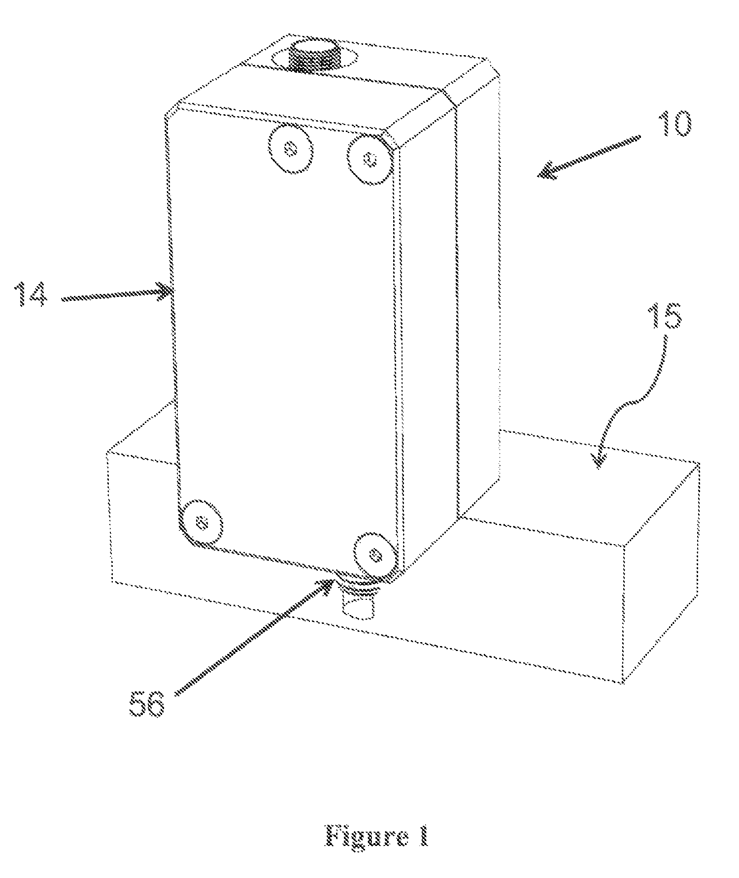
[0046]FIGS. 1-8 illustrate an exemplary embodiment of an energy harvester 10 in accordance with various aspects of the disclosure. According to some aspects, as shown in FIG. 1, an exemplary energy harvester 10 may include a housing 14 and a coupling arrangement 56 for coupling the housing 14 to a host structure 15.

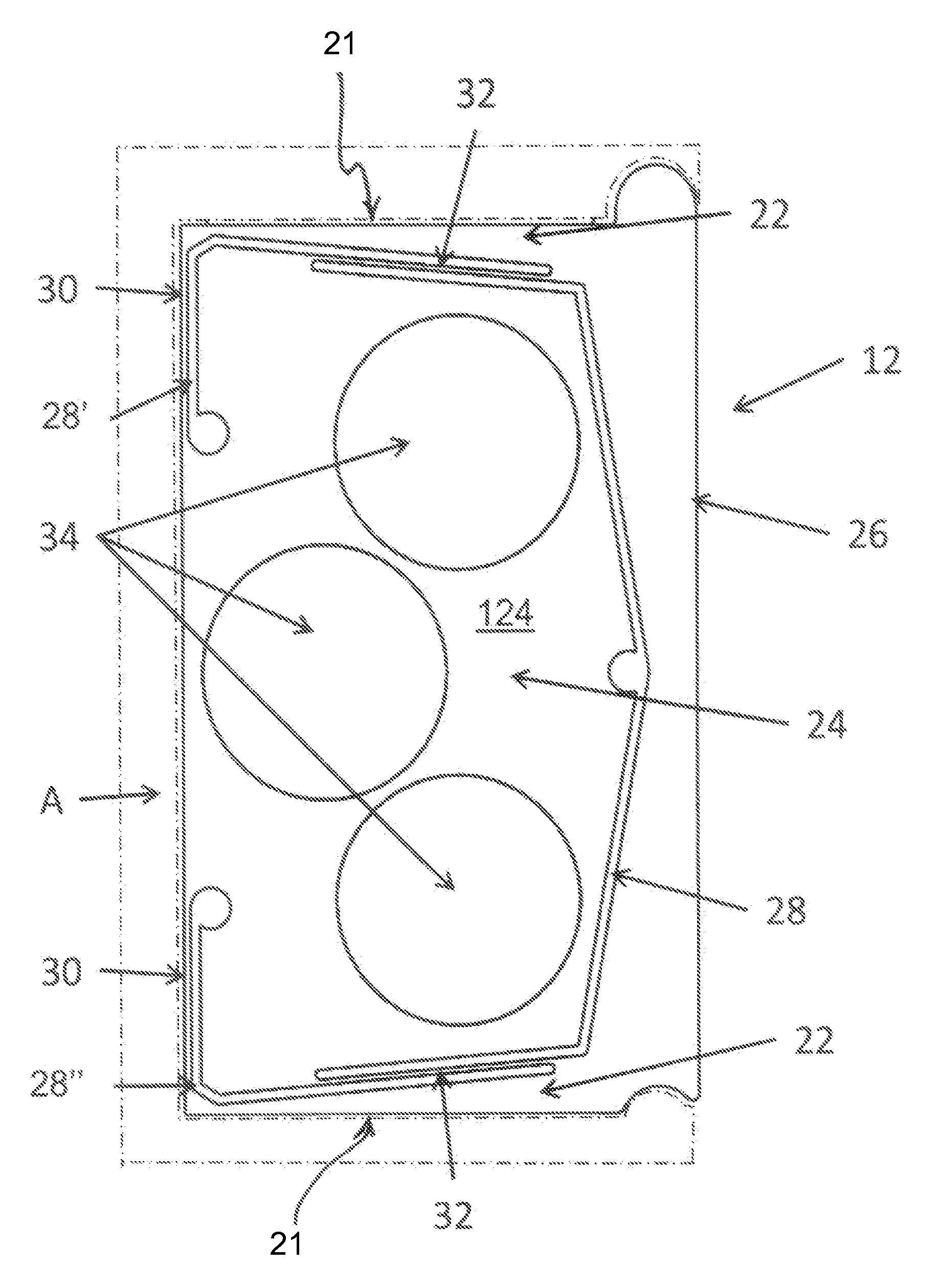
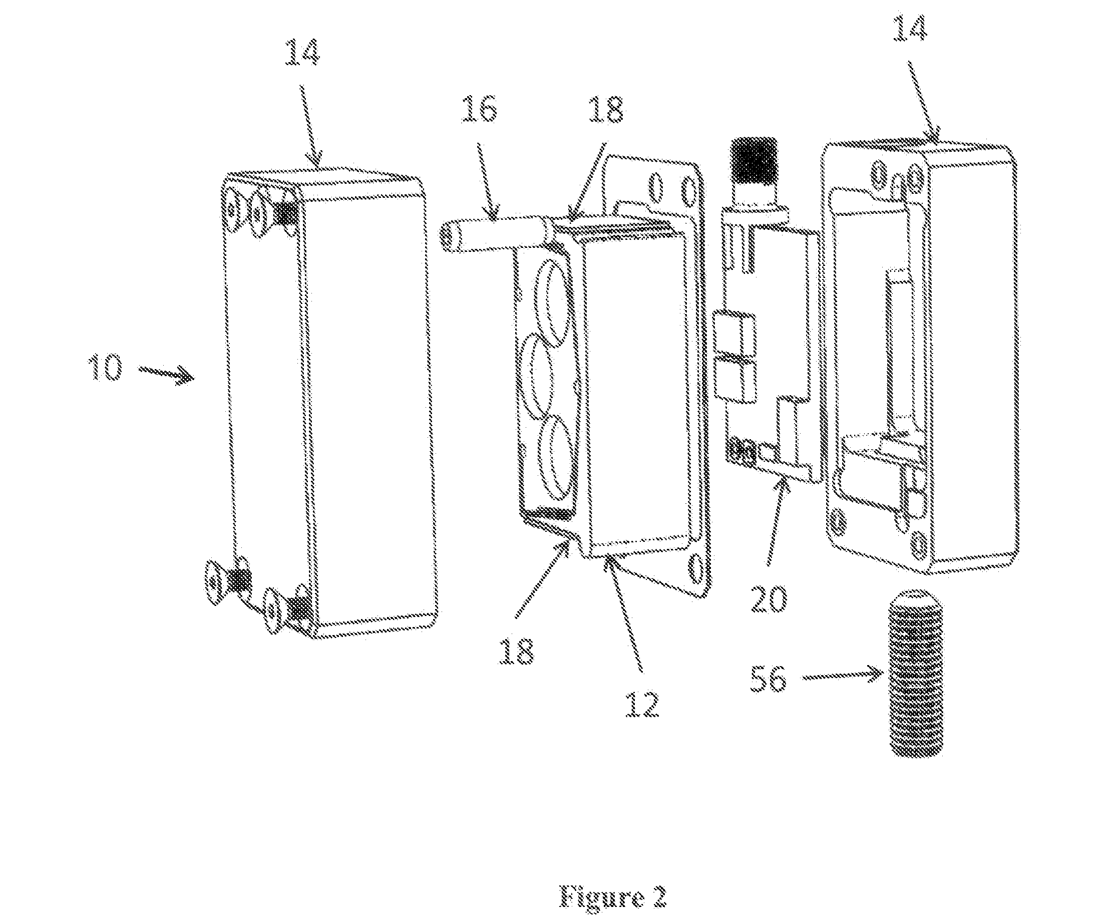
[0047]Referring to FIG. 2, the energy harvester 10 may further include a single degree of freedom resonator 12, a pin 16 (described in more detail below), electro-mechanical transducers 18, and electronic circuitry 20. In an exemplary embodiment, the electromechanical transducers 18 are piezoelectric elements. Referring now to FIG. 3, in an exemplary embodiment the resonator 12 may ...


PUM


Abstract

An energy harvesting device utilizing a monolithic, mesoscale, single-degree-of-freedom inertial based resonator in which the support structure, beam-spring, and proof mass are a single component without joints, bonds, or fasteners. Frequency tuning features include holes in the proof mass in which mass can be added to change the devices resonance frequency as well as levers which add curvature to the beam-spring system and adjust system stiffness. Robustness is increase by designing the resonator to exhibit nonlinear behavior such that its power density is maximized for low vibration amplitudes and minimized for high amplitudes. The device structural resonance modes are designed to be much higher than the resonators proof mass-spring resonance frequency. Electromechanical transducers are used to convert the resonators mechanical energy to electrical energy. Electrical circuitry is included to extract and condition the electrical charge.

Description

GOVERNMENT LICENSE RIGHTS[0001]This invention was made with United States government support under U.S. Navy SBIR Award No. N00014-09-C-0139. The government has certain rights in this invention.CROSS-REFERENCE TO RELATED APPLICATION[0002]The present disclosure is related to copending U.S. patent application Ser. No. 13 / 731,694, entitled “Wireless Energy Harvester Power Accelerometer”, filed concurrently with the present application, the disclosure of which is incorporated herein by reference.TECHNICAL FIELD[0003]The present disclosure relates generally to apparatuses and methods for generating electricity by induced vibration and, more specifically, to an apparatuses and methods for generating electrical energy with a monolithic meso-scale inertial-based energy harvesting device having a beam spring structure.BACKGROUND[0004]Energy harvesters are devices that generally extract a fraction of energy flowing as a result of other systems' or environments' operational conditions. For exa...

Claims


Application Information

Patent Timeline
Patent Type & Authority Patents(United States)
IPC IPC(8): H02N2/00H01L41/113H02N11/00
CPCH02N11/002H02N2/188H10N30/306
Inventor LOVERICH, JACOB J.GEIGER, RICHARD T.WENNER, STEPHEN J.
Owner KCF TECHNOLOGIES
Why Eureka
Try Eureka