Wave energy machine

a wave energy machine and wave energy technology, applied in the field of wave energy machines, can solve the problems of device overstress, enormous power resources of deep water wave, etc., and achieve the effect of limiting the growth of energy and stiff outer walls

Active Publication Date: 2016-10-11
CHECKMATE
View PDF9 Cites 0 Cited by
  • Summary
  • Abstract
  • Description
  • Claims
  • Application Information

AI Technical Summary

Benefits of technology

[0023]It is a particular advantage of the invention that the energy harnessing means, in use, extracts energy from the fluid held by the chambers as each bulge wave travels along the length of the channel. This helps to prevent a bulge wave from growing too large or placing any undue stress on the outer wall.
[0024]The extraction of energy from the fluid in each of the chambers therefore serves to limit the growth of the energy conveyed by a bulge wave as this travels along the length of the channel.
[0025]In general, the device may comprise buoyancy means so that, in use, the wave energy device is only partially submerged. The bulge wave is then generated by water flowing downhill within the channel. This is in contrast to the prior art in which a fully distensible outer wall is fully submerged and substantially level, the bulge wave then being generated by pressure gradients as wave pass over the submerged tube.
[0026]The fluid may be compressible or substantially incompressible. When the fluid is a compressible gas, the chambers may advantageously be provided in an upper portion of the tubular body, to aid with buoyancy and to keep the tubular body correctly oriented so that the bulge wave pressure acts upwards on the chamber.
[0027]Preferably, each of the inner walls forming a chamber is affixed to the outer wall around the periphery of the corresponding chamber. The inner wall may also be saddle-shaped.
[0028]The stiffness of the outer wall in the circumferential direction is preferably greater than the stiffness of the outer wall in the longitudinal direction, so that the tubular body may follow the undulations of the passing waves while substantially containing the bulge wave within the outer wall.

Problems solved by technology

Deep water wave power resources are truly enormous.
Large storm waves pose a challenge to wave power development.
This presents a problem in that the device may be over-stressed in very high seas.

Method used


Image

  • Wave energy machine
  • Wave energy machine
  • Wave energy machine

Examples


Embodiment Construction

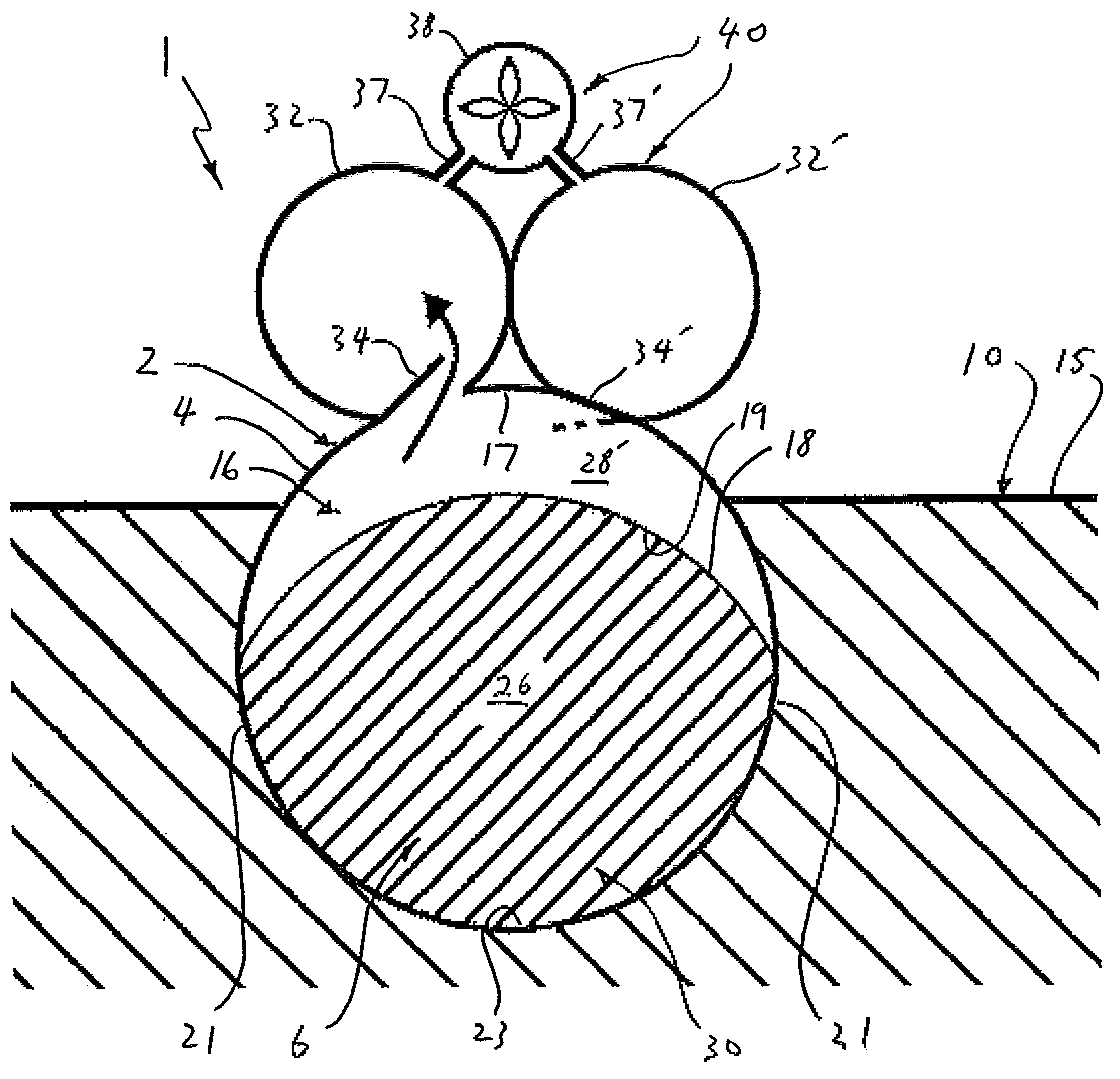
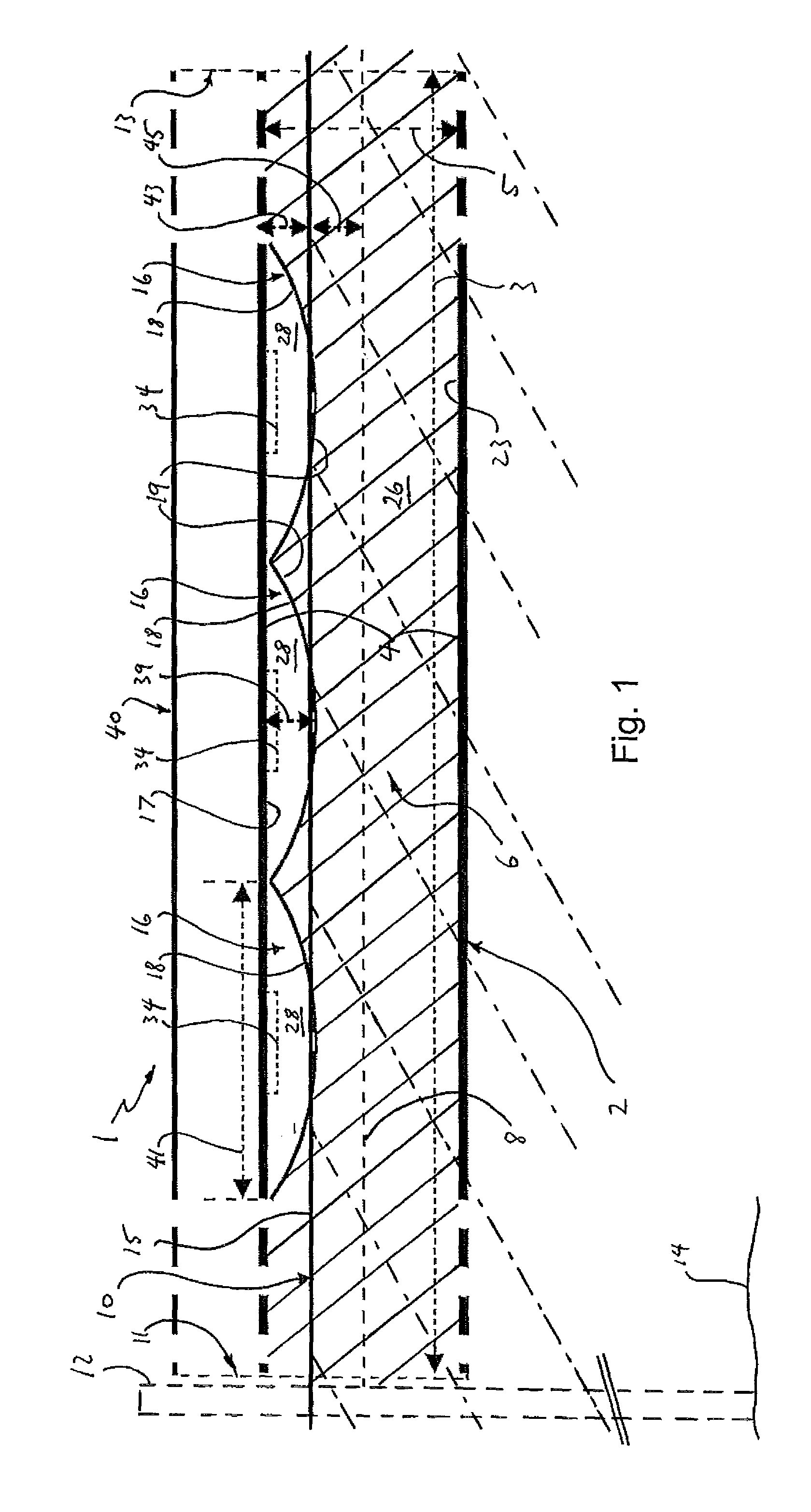
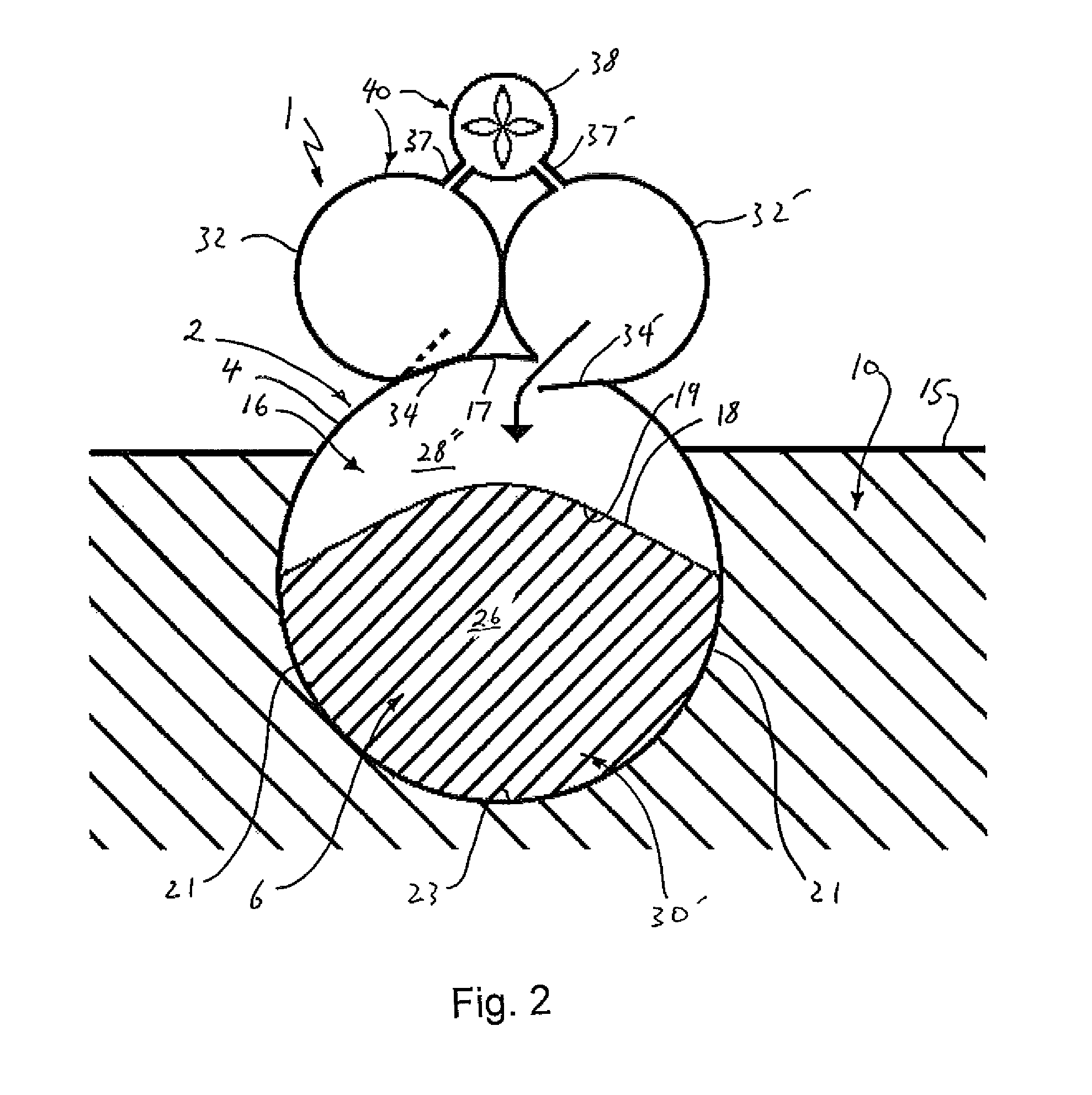
[0047]FIG. 1 shows schematically a cross-section through an elongate wave energy device 1 for extracting energy from surface waves in a body of water 10 for example the open sea. The device 1 has an elongate and flexible tubular body 2 with a substantially circular cross-section (see FIGS. 2 and 3) and that has an outer wall 4 and within the outer wall a channel 6 that extends unobstructed along the length of the tubular body. The tubular body 2 has a length 3 of 400 m and a width 5 of 2.5 m. The channel extends fully around a central axis 8 of the tubular body 2 and is formed between two layers of the tubular body 2.

[0048]The tubular body is moored at one end 11 to a mooring, for example a pile 12 or other structure secured to the seabed 14. The tubular body is free to swing around the mooring depending on the wave direction, with an opposite end 13 floating freely on the sea surface 15. The channel 6 is open at both ends 11, 13 of the body 2.

[0049]Also contained within the tubular...


PUM


Abstract

This invention relates to a device and method for extracting energy from surface waves in a body of water, for example, the sea. A wave energy device (1) for extracting energy from surface waves in a body of water includes an elongate and flexible tubular body (2) having an outer wall (4) and within the outer wall a channel (6) that extends along the length of the tubular body (2). The device is positioned in a body of water so that, in use, the elongate body (2) extends along the water surface (15) in the direction of surface waves with water contained within the channel being driven to form a series of bulge waves that travel along the length of the channel as the tubular body flexibly follows the movement of the waves. The device harnesses energy from the bulge waves for providing useful power.

Description

BACKGROUND[0001]a. Field of the Invention[0002]This invention relates to a device and a method for extracting energy from surface waves in a body of water, for example, the sea.[0003]b. Related Art[0004]Deep water wave power resources are truly enormous. It has been estimated that The UK has an estimated recoverable resource of between 50-90 TWh of electricity a year; this is roughly 15-25% of the current UK electricity demand. Worldwide, the useful worldwide resource has been estimated to be greater than 8700 TWh per year.[0005]One type of wave energy device is disclosed in patent document WO 2007 / 088325 A1. This relates to a distensible tube wave energy converter, formed from an elongate distensible tubular body which has an elastic outer wall entrains a bulge wave generated by wave passing over the device. Large storm waves pose a challenge to wave power development. Because the wave energy power take off is at one or both ends, the bulge wave energy at the take off will increase...

Claims


Application Information

Patent Timeline
Patent Type & Authority Patents(United States)
IPC IPC(8): F03B13/24F03B13/14F03B13/22F03B13/18
CPCF03B13/188F03B13/148F03B13/22F03B13/24F05B2250/611Y02E10/38Y02E10/30
Inventor RAINEY, RODERICK CHARLES TASMAN
Owner CHECKMATE
Why Eureka
Try Eureka