Device for determining a shaft center deviation

a technology of center deviation and device, which is applied in the direction of mechanical energy handling, mechanical equipment, instruments, etc., can solve the problems of difficult manufacturing of hall sensors and therefore high cost, and achieve the effect of cost-effective and accura

Inactive Publication Date: 2010-05-04
SIEMENS AG
View PDF9 Cites 16 Cited by
  • Summary
  • Abstract
  • Description
  • Claims
  • Application Information

AI Technical Summary

Benefits of technology

[0005]Therefore, the invention is based on the object of specifying a device for determining a shaft center deviation which makes it possible to determine a shaft center deviation in a more cost-effective and accurate manner.
[0013]As a result, the device can advantageously be produced in a cost-effective manner and has a very high level of accuracy. Furthermore, there is no need for a zero point adjustment operation and aging of the material does not influence the measurement accuracy. In this case, |Perr−Paus|=1 means that Perr and Paus differ by precisely 1. In this case, the shaft must be at least as long as the stator and may be fastened, at least one end, to further elements or may merge into further elements. In this case, the elements may be made from a different material and may have a different shape.

Problems solved by technology

However, the disadvantage is that the Hall sensors are difficult to manufacture and are therefore expensive and that a zero point adjustment operation must take place before the sensor is started.
However, under certain circumstances, the zero point adjustment operation must be repeated after a certain operating time since the material of the sensor ages.
Accordingly, the use of Hall sensors also results in inaccuracies when determining the shaft center deviation.

Method used


Image

  • Device for determining a shaft center deviation
  • Device for determining a shaft center deviation
  • Device for determining a shaft center deviation

Examples


Embodiment Construction

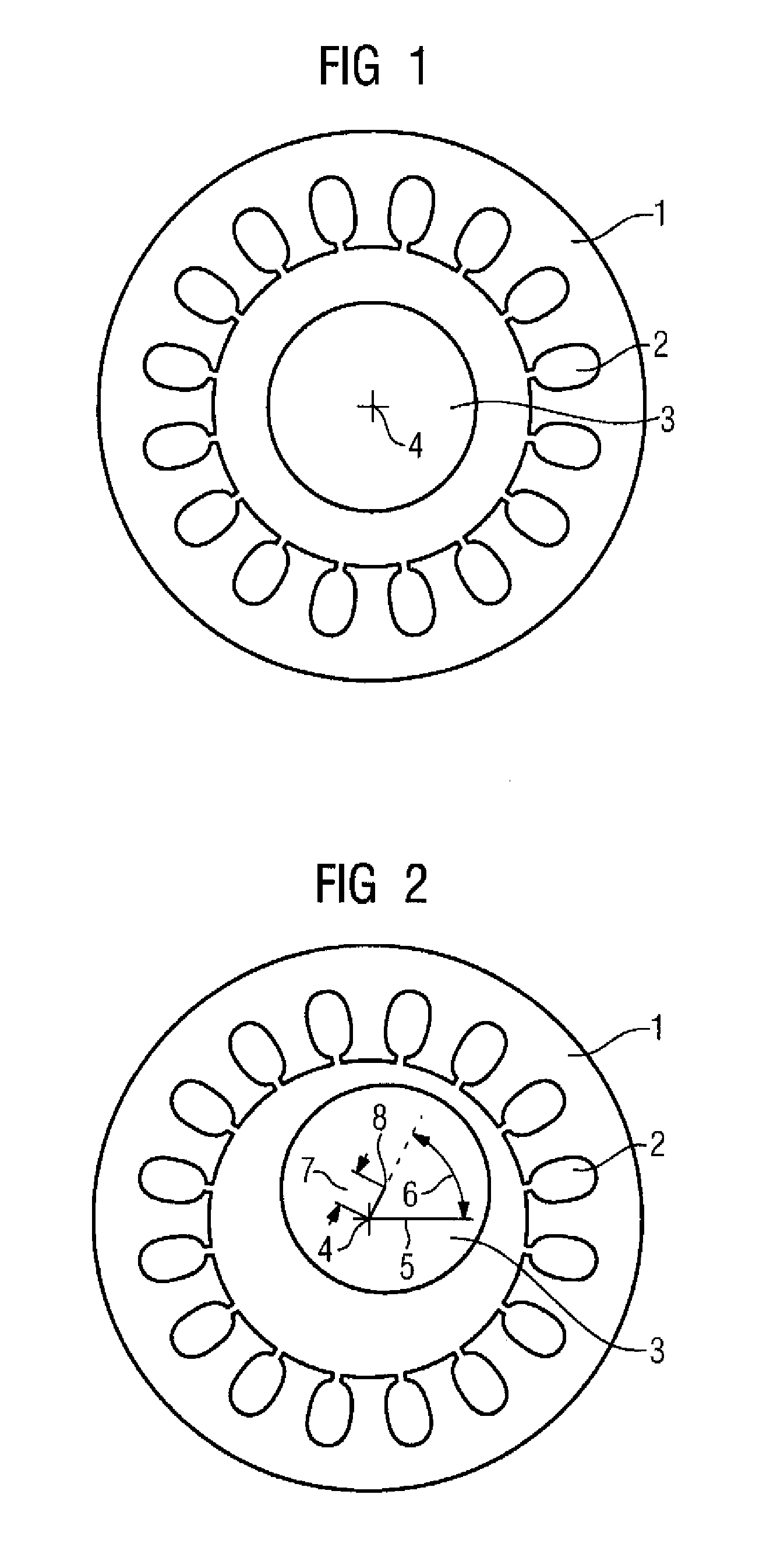
[0030]FIG. 1 shows a stator 1 of the inventive device with a central shaft 3. The stator 1 has slots 2 into which the excitation winding system and the output winding systems are inserted. In this example, the shaft 4 is situated in the center of the stator 1, that is to say the center of the shaft is precisely in the center 4 of the stator.

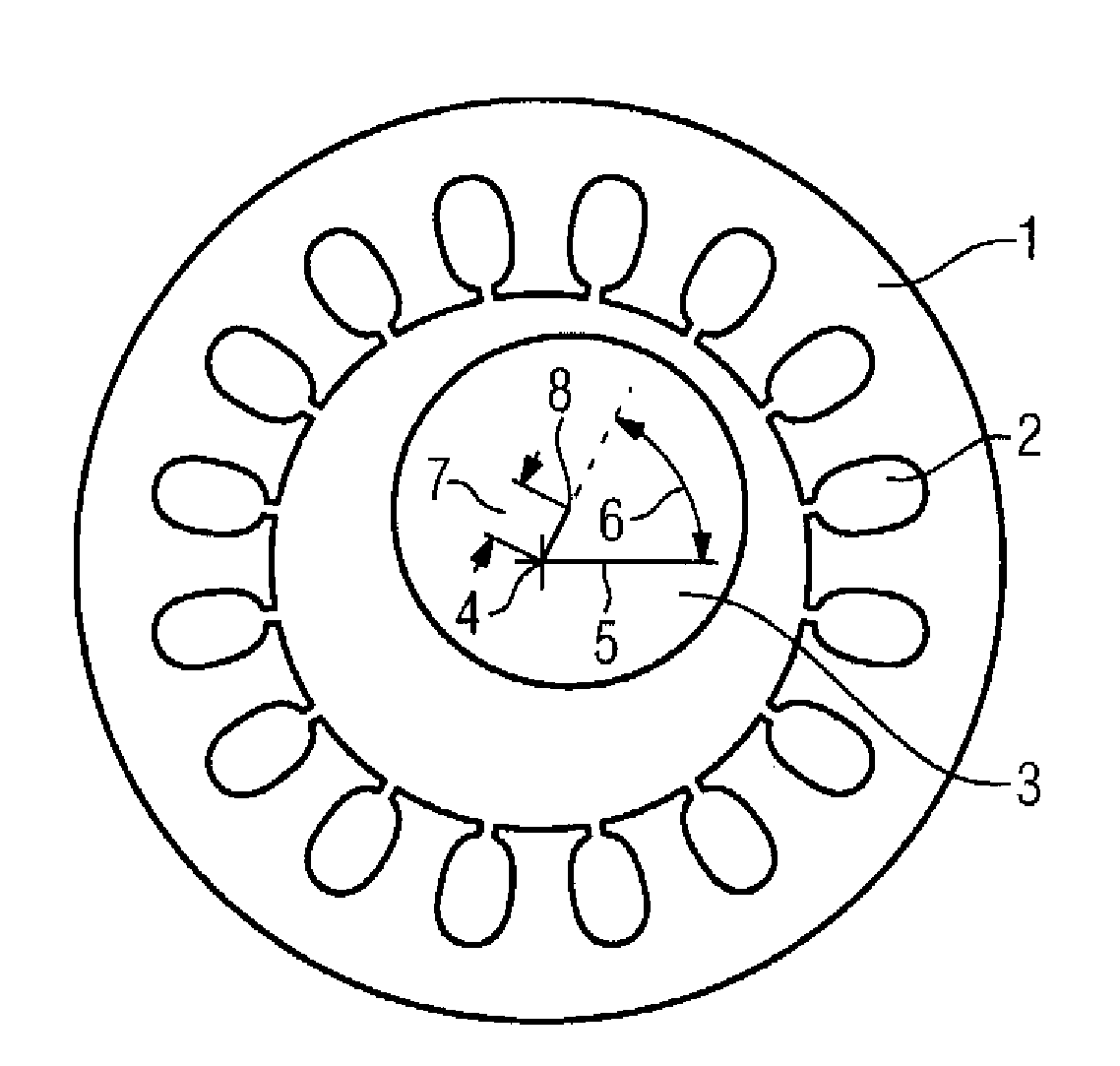
[0031]FIG. 2 shows the stator 1 of the inventive device with a shaft 3 which is not central. In this example, the center 8 of the shaft 3 is situated beside the center 4 of the stator. The shaft 3 center deviation can be expressed by the deviation 7 from point 4 to point 8 and by the angle 6 of the deviation 7 of the stator, measured from a reference line 5 which runs through the center 4 of the stator.

[0032]The inventive device determines the deviation 7 and the angle 6 and thus the center deviation of the shaft 3 in the stator 1. This is effected by feeding an AC voltage at a frequency of, for example, 2 to 10 kHz to the excitation winding syst...


PUM


Abstract

The invention relates to a device for determining the center deviation of a shaft (3) comprising a stator (1) in which an exciting winding system provided with a number of Perr pole pairs is arranged and two output winding systems provided with respective number of Paus pole pairs, wherein the output winding systems are remotely arranged with respect to each other in the stator, the shaft (3) is movably placed in the stator (1) in such a way that it makes it possible to display the shaft center deviation, when ¦Perr−Paus¦=1, an air gap is situated between the stator (1) and the shaft (3), the device voltage source is arranged for supplying the exciting winding system with an alternating voltage and the device output evaluation system is provided for determining the center deviation according to the voltage induced by the output winding systems.

Description

BACKGROUND OF THE INVENTION[0001]The invention relates to a device for determining a shaft center deviation and to a method for determining a shaft center deviation.[0002]Magnetic bearings can be subdivided into passive magnetic bearings and active magnetic bearings. In the case of passive magnetic bearings, use is either made of the repelling or attracting forces which occur between permanent magnets or of the attraction forces between permanent magnets and ferromagnetic materials. In the case of active magnetic bearings, the magnetic field required is generated with the aid of electromagnets. The magnetic field and thus the currently acting forces can be changed by varying the current in the coils of the electromagnets. In order to be able to mount a machine part in such a manner, a control operation which ensures that the currently required bearing forces are available is always required. The controlled variable is the center deviation of the part to be mounted or of the shaft to...

Claims


Application Information

Patent Timeline
Patent Type & Authority Patents(United States)
IPC IPC(8): H02K7/09
CPCF16C32/0446H02K11/0031G01B7/312H02K7/09H02K11/225
Inventor BRAUN, MATTHIASVOLLMER, ROLF
Owner SIEMENS AG
Why Eureka
Try Eureka