Sliding operating device

a technology of operating device and sliding shaft, which is applied in the direction of mechanical actuators, mechanical apparatus, contact mechanisms, etc., can solve the problems of external dust undetected in the case, and achieve the effects of reducing cost, simple construction, and reliable dust prevention

Inactive Publication Date: 2010-05-04
YAMAHA CORP
View PDF12 Cites 11 Cited by
  • Summary
  • Abstract
  • Description
  • Claims
  • Application Information

AI Technical Summary

Benefits of technology

[0006]In view of the foregoing, it is an object of the present invention to provide an improved sliding operating device which achieves reliable dust prevention with a simple construction and at reduced cost.
[0008]According to the present invention, the top plate portions of the first case half and second case half are displaced from each other, in the direction vertical to the upper surface of the case, in an upper surface area of the case, and at least the respective edge regions of the top plate portions of the first and second case halves overlap with each other in the direction vertical to the upper surface of the case. Even where the top plate portions have mutually-overlapping edge regions like this, the free end portion of the operating section having the intermediate bent portion can be projected outwardly of the case through the gap in the overlapping regions. The free end portion of the operating section is projected or exposed outwardly from the edge region of one of the top plate portions located outwardly of the other top plate portion, and there is a possibility of external dust undesirably entering the case through the gap via the projected or exposed portion. However, by virtue of the mutually-overlapping edge regions of the top plate portions of the first and second case halves, i.e. because the inner top plate portion is located immediately beneath the other or outer top plate portion, dust having entered the case via the projected or exposed portion is effectively prevented, by the inner top plate portion, from being sent further inwardly beyond the inner top plate portion. Such arrangements of the present invention can prevent external dust from falling onto the moving member and movement guide section within the case, thereby achieving superior dust prevention. Because such dust prevention can be achieved without any extra component part, such as a blindfold plate, the present invention can be simple in construction and can reduce the necessary cost for the dust prevention.
[0009]For example, in a case where the movement guide section is in the form of a shaft extending in the direction of sliding movement of the moving member and the moving member is slidably supported by the shaft, the shaft can be easily positioned beneath the inner top plate portion, and the inner top plate portion can prevent dust etc. from getting into an area of sliding contact between the moving member and the shaft.
[0010]Preferably, at least one of the top plate portions of the first case half and the second case half, which is located inwardly of the other of the top plate portions, slants transversely across the direction of sliding movement of the moving member. Thus, dust etc. having entered the case via the projected or exposed portion can be not only effectively prevented by the inner top plate portion from being sent further inwardly but also caused to fall along the slanting top plate portion, so that the dust etc. will not accumulate on the inner top plate portion. The inner top plate portion may slant in any suitable direction. For example, if the inner top plate portion slants in such a manner that the above-mentioned edge region of the inner top plate portion is located lower than the other edge region, dust will fall along the slanting inner top plate portion onto the bottom surface of the case. If, on the other hand, the inner top plate portion slants in such a manner that the above-mentioned edge region of the inner top plate portion is located higher than the other edge region, dust will fall, along the slanting inner top plate portion and then along a side surface of the case, onto an area outside the case.
[0012]For example, the engagement structure comprises a recessed portion provided in the side plate portion of one of the first and second case halves and a projecting portion provided on other of the first and second case halves. The first and second case halves engage with each other by the projecting portion being fitted in the recessed portion; in this manner, the case is assembled. When the first and second case halves are to be joined with each other, the projecting portion provided on the top plate portion of the first or second case halve is caused to run over a wall surface area of the top plate portion of the second or first case half, against frictional resistance, until it reaches the recessed portion. Once the projecting portion reaches the recessed portion in the top plate portion of the second or first case half, it is firmly fitted into the recessed portion. Thus, when the projecting portion is to be disengaged from the recessed portion, it must be caused to run over the wall surface area of the top plate portion of the second or first case half, against frictional resistance, in a direction opposite the direction at the time of the joining; namely, the first and second case halves can never be easily disengaged from the recessed portion. As a consequence, the firm fitting engagement between the first and second case halves can be maintained reliably. Besides, no screw or other fastening member is required for the assemblage of the first and second case halves and operation for disassembling the first and second case halves can be simplified, so that maintenance can be effected with an enhanced operability.
[0013]Preferably, the top plate portion, slanting transversely across the direction of sliding movement, has raised portions formed on opposite end regions thereof spaced apart in the direction of sliding movement of the moving member. Thus, even when dust etc. accumulated on the inner top plate portion has been swept together in the direction of sliding movement of the moving member, the dust etc. can be effectively prevented, by the raised portions formed on the opposite end regions, from falling outside the case, so that the dust etc. falls only along the slanting top plate portion. As a consequence, the present invention can prevent even more effectively influences of dust etc. on the moving member and movement guide section within the case. The raised portions of the inner top plate portion may be held in abutting engagement against the lower surface of the outer top plate portion, in which case the first and second case halves can be appropriately positioned relative to each other in the vertical direction.

Problems solved by technology

The free end portion of the operating section is projected or exposed outwardly from the edge region of one of the top plate portions located outwardly of the other top plate portion, and there is a possibility of external dust undesirably entering the case through the gap via the projected or exposed portion.

Method used


Image

  • Sliding operating device
  • Sliding operating device
  • Sliding operating device

Examples


first embodiment

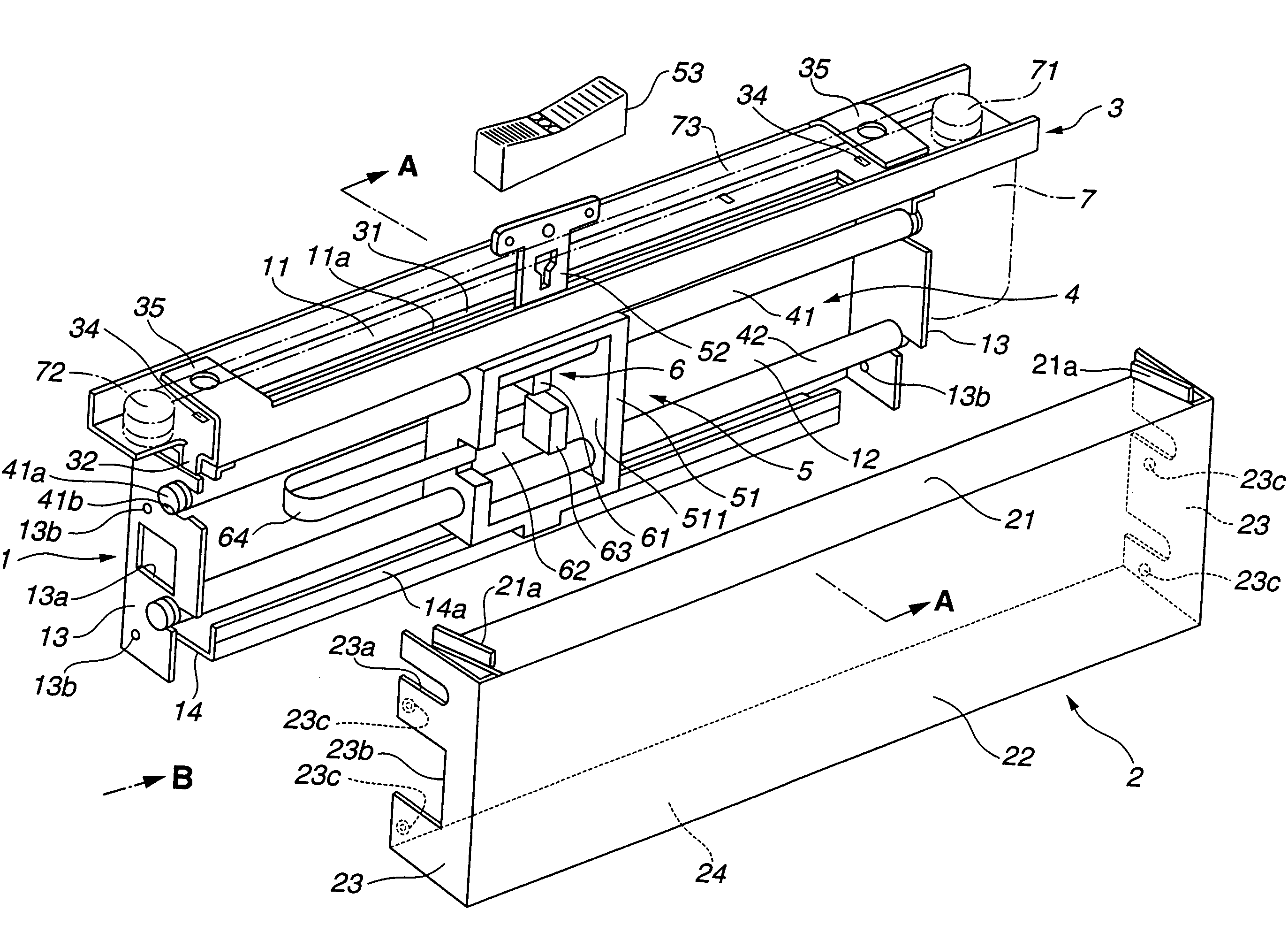
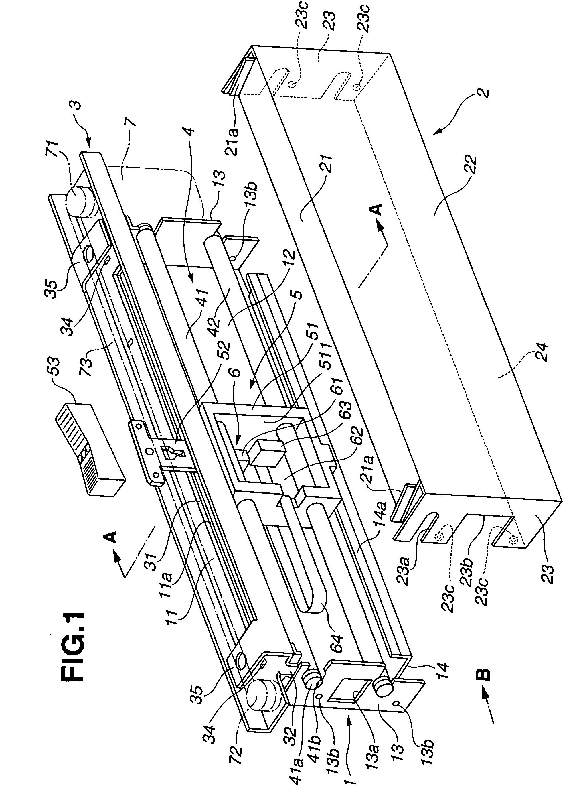
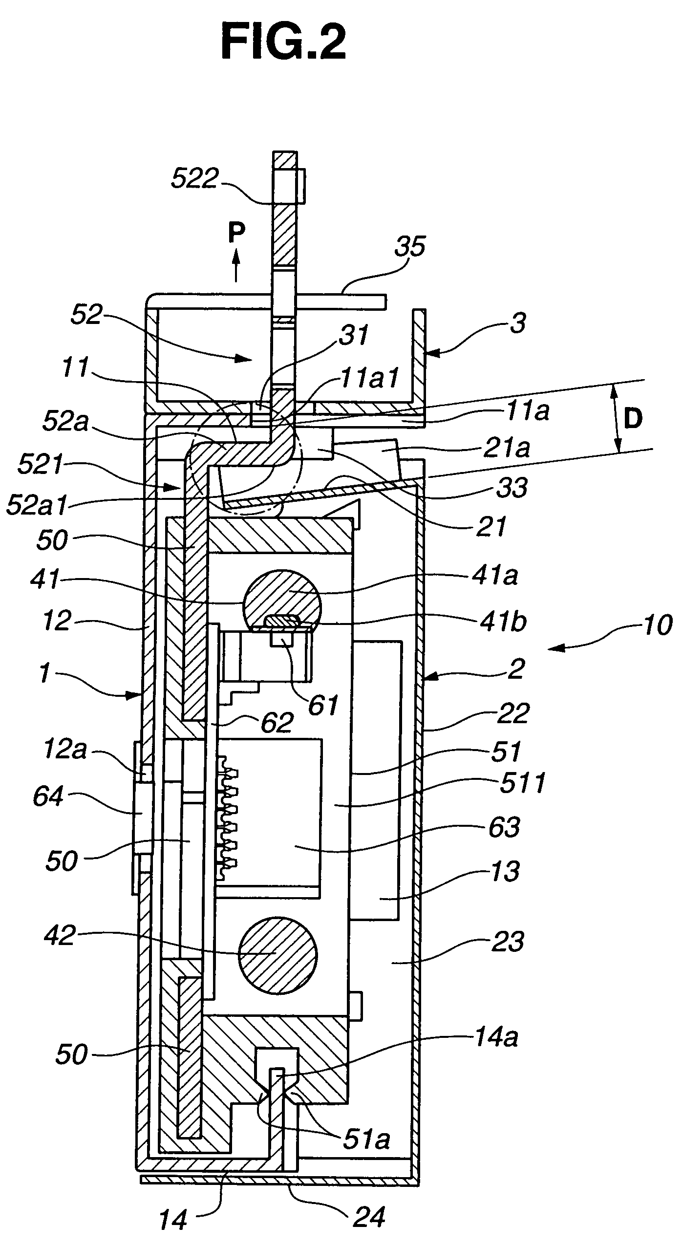
[0025]FIG. 1 is an exploded perspective view showing relevant sections of a sliding volume control device constructed as a sliding operating device of the present invention. FIG. 2 is a view of the sliding volume control device taken along the A-A line of FIG. 1, and FIG. 3 is a view of the sliding volume control device taken in the direction of arrow B. This sliding volume control device includes a frame 1 as a first case half, a cover 2 as a second case half, and a motor mounting member 3. The cover 2 and motor mounting member 3 may be formed by cutting and bending of a metal plate. The frame 1 and cover 2 are formed into a rectangular thin box shape. The motor mounting member 3 is formed into an elongated shape having a channel sectional shape.

[0026]The frame (first case half) 1, which is formed into a substantial box shape having an opening in one side thereof, has a top plate portion 11, case side surface portion 12, case end surface portions (i.e., side plate portions of the c...

second embodiment

[0042]In the cover 2′ of the second embodiment, as seen in FIG. 7, the top of the case end surface portion (i.e., side plate portion of the case half) 23′ is located at generally the same height as the top of the raised portion 21a′ of the top plate portion 21′. Slight gap is formed between the outer positioning piece 32′ and the end surface portion (i.e., side plate portion of the case half) 13 of the frame 1. When the cover 2′ is fitted over the frame 1, the top of the case end surface portion 23′ of the cover 2′ is fitted between the outer positioning piece 32′ and the end surface portion 13. Further, the inner positioning piece 33′ of the motor mounting member 13 is abutted against the outer surface of the raised portion 21a′ of the cover 2′.

[0043]The top plate portion 21′ slants downwardly from the upper end of the case side surface portion 12 of the frame 1 toward the case side surface portion 22′ of the cover 2′. Namely, the top plate portion 21′ in the second embodiment slan...


PUM


Abstract

A case includes first and second halves, each having an opening in its one side, combined together with the openings opposed to each other. A moving member is accommodated within the case and slidingly movable along a movement guide. An operator is connected to the moving member. The operator has a proximal end connected to the moving member, a free end projecting outwardly from an upper surface of the case, and a bent portion bent between the both ends. Tops of the first and second halves are displaced from each other, in a direction vertical to the upper surface, to form a gap permitting entry of the operator. Edge regions of the tops of the both halves overlap with each other in the direction vertical to the upper surface, and the bent portion is bent so that the free end projects outwardly through the gap in the overlapping regions.

Description

BACKGROUND OF THE INVENTION[0001]The present invention relates to a sliding operating device which can be suitably used to set a parameter or the like, corresponding to user's operation, by moving an operating-position setting section (moving member) in response to operation of a sliding-type operator and detecting a position of the operating-position setting section.[0002]Examples of the conventionally-known sliding operating devices for use in mixing consoles etc. include the one disclosed in Japanese Patent No. 3273422. The disclosed sliding operating device integrally includes a lever having a knob portion and a slider holder for holding slider pieces opposed to a resistor board. The lever and slider holder are slidably supported on guide shafts. Through manual operation of the knob portion or through driving by a motor, the slider holder moves so that a parameter or the like is set in accordance with a position of the slider pieces relative to the resistor board.[0003]Further, ...

Claims


Application Information

Patent Timeline
Patent Type & Authority Patents(United States)
IPC IPC(8): H01C10/30
CPCH01C10/14H01C10/30
Inventor KATO, KOJIRO
Owner YAMAHA CORP
Why Eureka
Try Eureka