Imaging optical system

an optical system and optical system technology, applied in optics, instruments, lenses, etc., can solve the problems of chromatic aberration, low screen resolution, and large pixel size of lenses applied to camera modules designed as low pixel grades, and achieve superb chromatic aberration correction, increase resolution, and high performance and compactness.

Active Publication Date: 2010-05-04
SAMSUNG ELECTRO MECHANICS CO LTD
View PDF2 Cites 98 Cited by
  • Summary
  • Abstract
  • Description
  • Claims
  • Application Information

AI Technical Summary

Benefits of technology

[0009]An aspect of the present invention provides a high-definition imaging optical system ensuring high performance and compactness, and capable of increasing resolution and correcting chromatic aberration superbly, thereby improving color fringing in the case of indoor and outdoor photographing.

Problems solved by technology

That is, the lenses applied to the camera module designed as a low-pixel grade are relatively large in pixel size and require relatively low screen resolution.
However, the lenses applied to the camera module designed as a high pixel grade are small in pixel size and require very high screen resolution.
The imaging optical system configured with three lenses experiences difficulty in correction of chromatic aberration.

Method used


Image

  • Imaging optical system
  • Imaging optical system
  • Imaging optical system

Examples


first embodiment

[0128]Following Table 1 shows numeric values of the lens system according to a first embodiment of the invention.

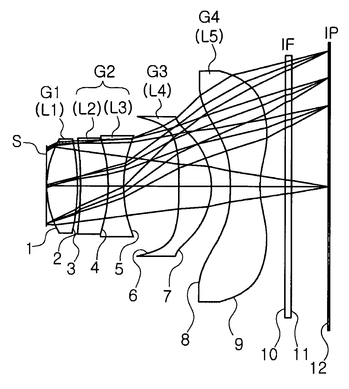
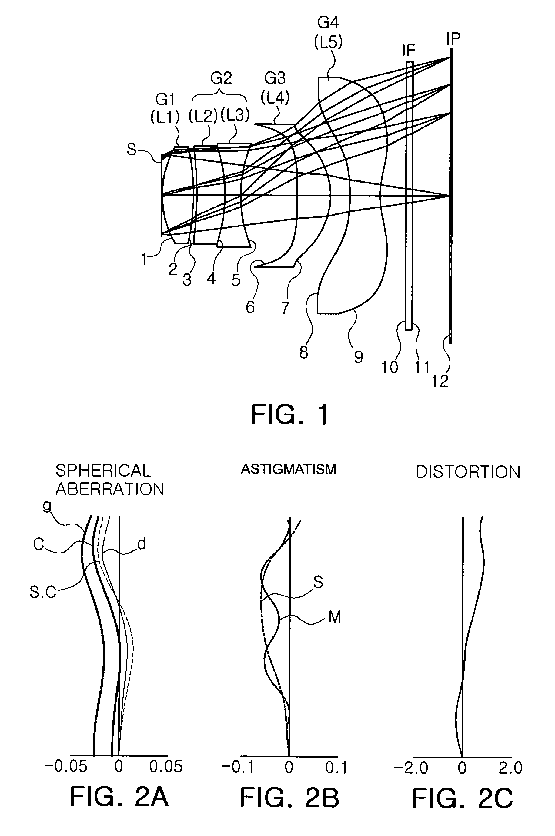
[0129]FIG. 1 is a view illustrating a lens arrangement of the high-definition imaging optical system according to the first embodiment of the present invention, and FIGS. 2A to 2C show aberrations of the embodiment shown in Table 1 and FIG. 1.

[0130]Also, in the drawings illustrating spherical aberration, a line d denotes a wavelength of 587.56 nm, a line g denotes a wavelength of 435.83 nm, a line c denotes a wavelength of 656.27 nm and S.C denotes sine condition. In the graphs illustrating astigmatism, “S” represents sagital and “T” represents tangential.

[0131]In the first embodiment, an effective focal length f is 5.686 mm, an F number Fno is 2.8, an angle of view is 64 degrees, a total length TL from an object-side surface of the first lens group to the image plane is 6.50 mm.

[0132]A focal length f1 of the first lens L1 is 3.74 mm, a combined focal length of the second...

second embodiment

[0136]Following Table 3 shows numeric values of the lens system according to a second embodiment of the present invention.

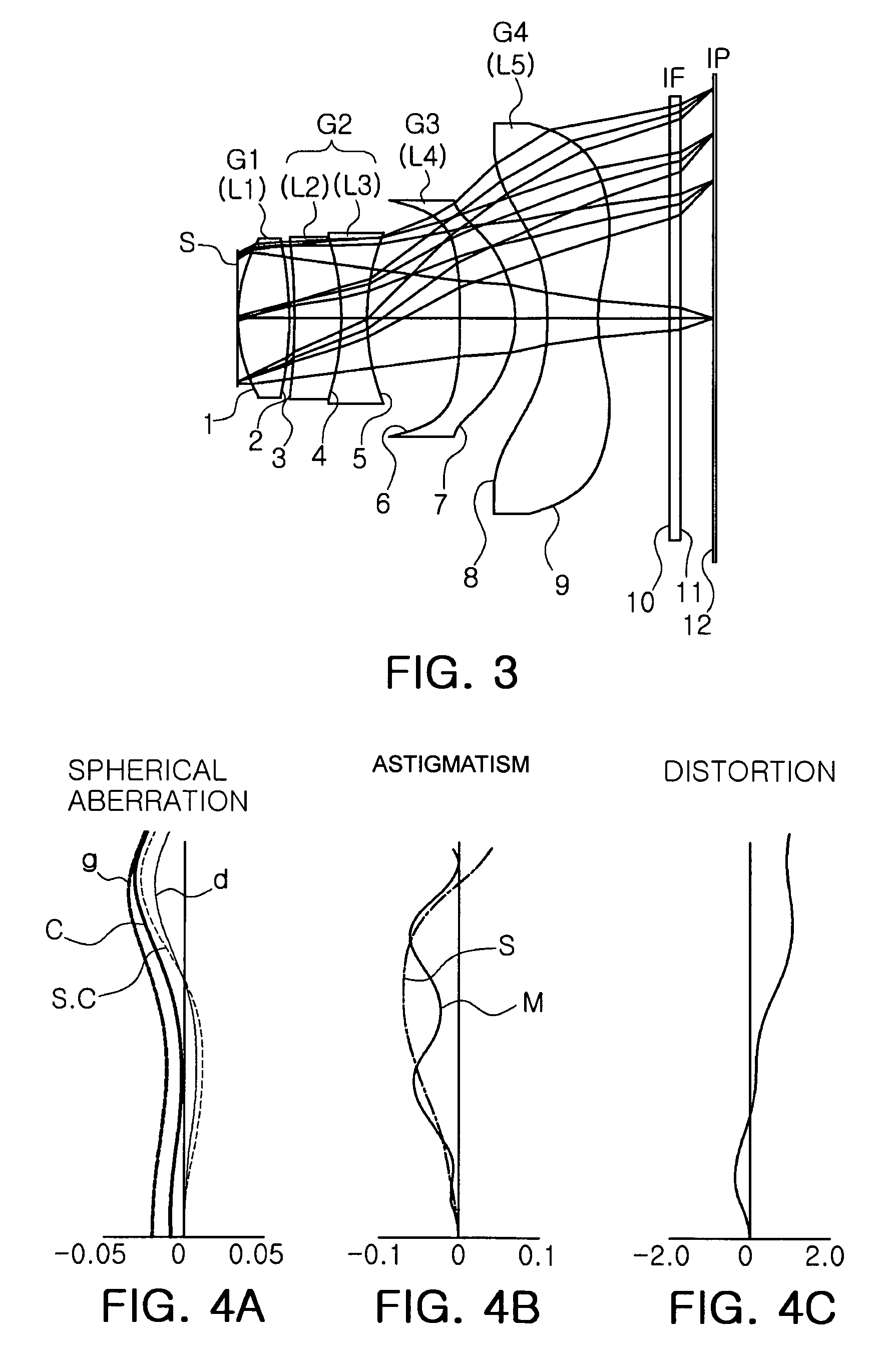
[0137]FIG. 4 is a view illustrating a lens arrangement of the high-definition imaging optical system according to the second embodiment of the invention, and FIGS. 4A to 4C show aberrations of the embodiment shown in Table 3 and FIG. 3.

[0138]In the second embodiment, an effective focal length f is 5.683 mm, an F number Fno is 2.8, an angle of view 2ω is 64 degrees, a total length TL from an object-side surface of the first lens group to the image plane is 6.50 mm.

[0139]A focal length f1 of the first lens L1 is 3.651 mm, a combined focal length of the second and third lenses L2 and L3, i.e., a focal length of the second lens group designated with f23 is −5.538 mm, a focal length f4 of the fourth lens L4 is 4.070 mm and a focal length f5 of the fifth lens L5 is −3.523 mm.

[0140]

TABLE 3Radius ofSurfacecurvatureThickness orRefractiveAbbeNo.(R)distance (t)index (Nd)num...

third embodiment

[0143]Following Table 5 shows numeric values of the lens system according to a third embodiment of the present invention.

[0144]FIG. 6 is a view illustrating a lens arrangement of the high-definition imaging optical system according to the second embodiment of the invention, and FIGS. 6A to 6C show aberrations of the embodiment shown in Table 5 and FIG. 5.

[0145]In the third embodiment, an effective focal length f is 5.699 mm, an F number Fno is 2.8, an angle of view 2ω is 64 degrees, a total length TL from an object-side surface of the first lens group to the image plane is 6.80 mm.

[0146]A focal length f1 of the first lens L1 is 3.554 mm, a combined focal length of the second and third lenses L2 and L3, i.e., a focal length of the second lens group designated with f23 is −5.029 mm, a focal length f4 of the fourth lens L4 is 2.776 mm and a focal length f5 of the fifth lens L5 is −2.646 mm.

[0147]

TABLE 5AbbeSurfaceRadius ofThickness orRefractivenumberNo.curvature (R)distance (t)index (N...


PUM


Abstract

There is provided a high-definition imaging optical system including: an aperture stop; a first lens disposed at an image side of the aperture stop, the first lens having a positive refractive power and having a convex object-side surface; a second lens disposed at an image side surface of the first lens; a third lens disposed at an image side surface of the second lens; a fourth lens having a convex image-side surface and having a positive refractive power; and a fifth lens having a concave image-side surface and having a negative refractive power, wherein a combined refractive power of the second and third lenses is negative. The optical system is high-performing and compact and can be further improved in resolution. Also, the optical system can correct chromatic aberration and improve color fringing in the case of indoor or outdoor photographing.

Description

CROSS-REFERENCE TO RELATED APPLICATIONS[0001]This application claims the priorities of Korean Patent Application No. 2007-113751 filed on Nov. 8, 2007 and Korean Patent Application No. 2007-135553 filed on Dec. 21, 2007, with the Korean Intellectual Property Office, the disclosures of which are incorporated herein by reference.BACKGROUND OF THE INVENTION[0002]1. Field of the Invention[0003]The present invention relates to an imaging optical system, and more particularly, to an imaging optical system with high resolution and compactness, which is mounted on a mobile telecommunication terminal and a personal digital assistant (PDA) and easily installed on a surveillance camera, a digital camera, and a personal computer (PC) camera to photograph an object more clearly.[0004]2. Description of the Related Art[0005]In general, a camera module lens for use in a mobile telecommunication terminal is formed of two and three lenses for a low-pixel grade, and three and four lenses for a high-pi...

Claims


Application Information

Patent Timeline
Patent Type & Authority Patents(United States)
IPC IPC(8): G02B9/60G02B3/02G02B9/34
CPCG02B9/34G02B13/006G02B13/004G02B9/60
Inventor PARK, CHEON HOJUNG, MOON SIK
Owner SAMSUNG ELECTRO MECHANICS CO LTD
Why Eureka
Try Eureka