Eureka AIR delivers breakthrough ideas for toughest innovation challenges, trusted by R&D personnel around the world.

Noise reduction systems and methods

Active Publication Date: 2010-05-04
ENTROPIC COMM INC
View PDF12 Cites 14 Cited by
  • Summary
  • Abstract
  • Description
  • Claims
  • Application Information

AI Technical Summary

Benefits of technology

[0010]Preferred embodiments of noise reduction systems and methods are disclosed. One method embodiment, among others, comprises transforming a residual signal to produce transform coefficients, and applyin

Problems solved by technology

As is known in the art, video recording is susceptible to different degrees and categories of noise that negatively affects video during compression and encoding.
Not only does noise degrade picture quality directly by virtue of its visual appearance, but the presence of noise degrades the quality of compressed video indirectly because, as is known in the art, an appreciable fraction of bit rate is consumed to compress the noise.
First, less bit rate is readily available to compress the real signal, resulting in increased compression impairments.
Second, as is known in the art, compressed noise often has a more disturbing appearance than uncompressed noise.
However, in a real environment, noise characteristics change over time or from video scene to video scene.
Therefore, static noise reduction methods are insufficient, especially in systems such as consumer digital video recorders in which a user is not always present to control the recorder settings to compensate for changes in noise sources that may comprise widely varying noise characteristics.
Furthermore, without additional controls, the classical motion-detecting temporal filter with a simple motion detector has difficulty separating moving objects from noise, and thus cannot always use the best noise reduction setting.
Specifically, in certain scenes, the classical motion-detecting temporal filter will filter too little, leaving more noise than necessary.
Alternatively, in other scenes, the temporal filter may filter too much, visibly smearing moving objects or creating “ghosts,” which appear as attenuated copies of moving objects trailing behind objects as they move within a video.

Method used


Image

  • Noise reduction systems and methods
  • Noise reduction systems and methods
  • Noise reduction systems and methods

Examples


Embodiment Construction

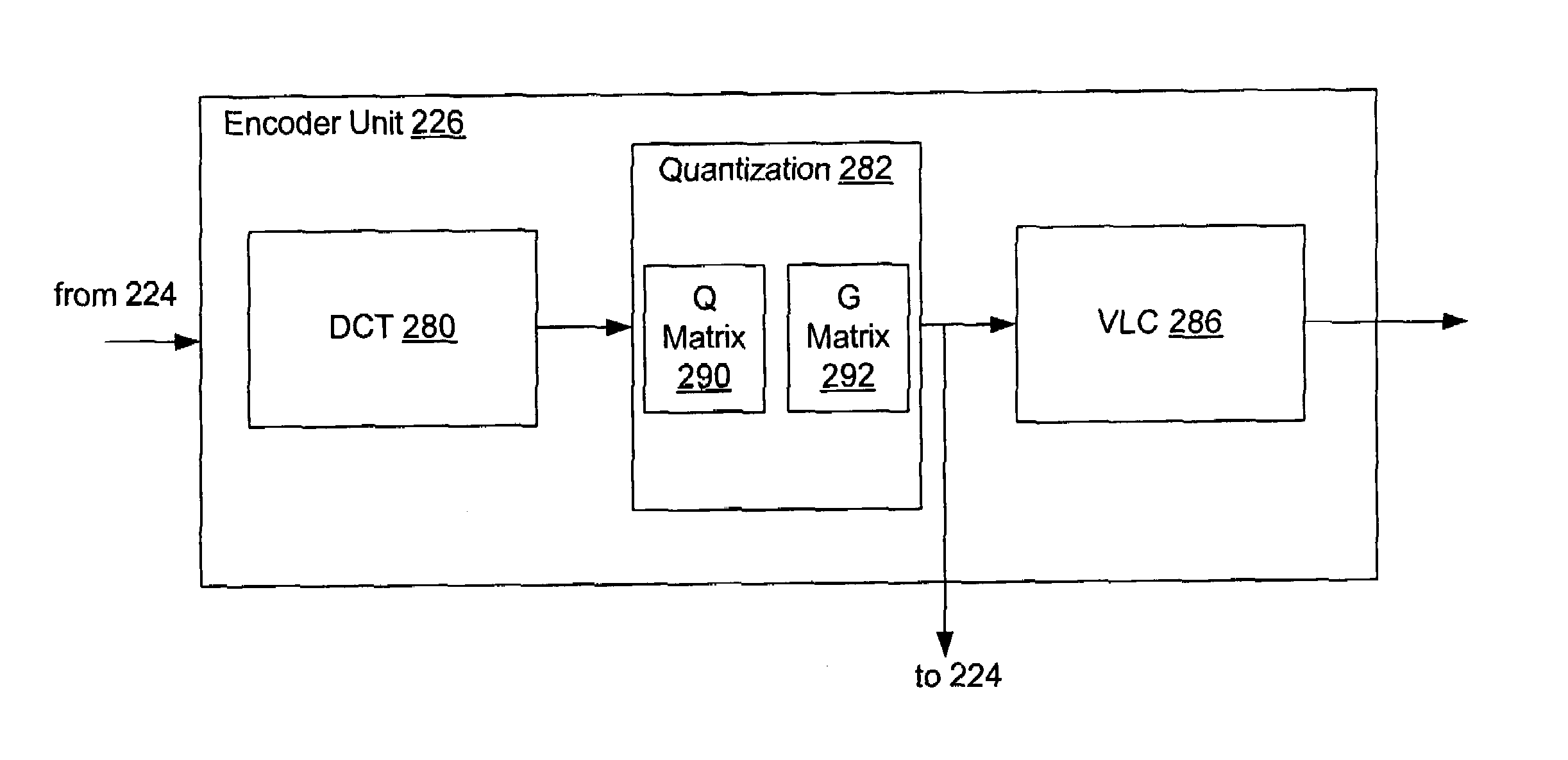
[0021]Disclosed herein are various embodiments of noise reduction systems and methods (herein, noise reduction system). Such a noise reduction system may employ one or more of motion adaptive temporal filtering, motion compensated temporal filtering, and noise measurement to perform noise reduction in video images. With regard to motion compensated temporal filtering, an embodiment of the noise reduction system performs motion compensated temporal filtering, wherein a block of discrete cosine transform (DCT) coefficients of motion compensated macroblocks are weighted according to one or more predefined 2-dimensional (2-D) weighting functions. The weighting functions comprise two parameters: one parameter controlling the shape and the other parameter controlling the magnitude. In one embodiment, the shape parameter may be user configurable, whereas the magnitude parameter can be calculated based upon a noise level measurement process as described below.

[0022]In the description that f...


PUM


Abstract

Embodiments of noise reduction systems and methods are disclosed. One method embodiment, among others, comprises transforming a residual signal to produce transform coefficients, and applying the transform coefficients to a quantization matrix and a configurable gain matrix to provide a frequency-selective weighting of the transform coefficients having a gain that is sensitive to noise levels.

Description

CROSS-REFERENCE TO RELATED APPLICATIONS[0001]This application is a continuation in part of U.S. utility application entitled, “System and Method For Automatically Reducing Noise For Video Encoding,” having Ser. No. 10 / 045,894, filed Oct. 29, 2001 now abandoned, which is incorporated by reference herein in its entirety.BACKGROUND OF THE INVENTION[0002]1. Field of the Invention[0003]The present disclosure generally relates to video encoding, and, more particularly, is related to the reduction of noise for video encoding.[0004]2. Related Art[0005]With advancements in technology, significant advances have been made in video processing technology. Analog video processing, which provides limited compression through typical single scan-line or one-dimensional (“1-D”) processing, has been surpassed by more efficient multiple scan-line or two-dimensional (“2-D”) digital video processing. Two-dimensional digital video processing has been surpassed by horizontal, vertical and temporal or three...

Claims


Application Information

Patent Timeline
IPC IPC(8): H04B1/66H04B1/69
CPCH04N19/147H04N19/86H04N19/80H04N19/117
Inventor HOANG, DZUNGHORIE, TOSHIHIROAPTE, ATUL
Owner ENTROPIC COMM INC
Why Eureka
Eureka Blog
Learn More