Encoding apparatus and method

a technology of video data and encoding apparatus, applied in the field of encoding apparatus and methods for video data, can solve the problems of large image deterioration, error generation between, image quality deterioration, etc., and achieve the effect of preventing image quality from deterioration and high spatial frequency

Inactive Publication Date: 2005-08-09
SONY CORP
View PDF9 Cites 34 Cited by
  • Summary
  • Abstract
  • Description
  • Claims
  • Application Information

AI Technical Summary

Benefits of technology

[0020]It is an object of the present invention to provide an encoding apparatus and an encoding method that prevent image quality from deteriorating by using a quantization matrix for quantization which is different from a quantization matrix for inverse quantization. Specifically, the encoding apparatus and the encoding method suppress components having high spatial frequencies, such as noise, by setting, in a quantization matrix for quantization, quantization coefficients for quantizing DCT coefficients having relatively high spatial frequencies to be greater than those for inverse quantization.

Problems solved by technology

This accumulates image distortions caused by quantization errors generated in image quantization and inverse quantization, which may cause great image deterioration.
Therefore, errors generated between the quantization computation and the inverse quantization computation are included as noise in the decoded video data.
The main cause of image quality deterioration is that noises (called “mosquito noise”) having high frequency components increase.
Accordingly, in repeated implementation of the encoding and decoding based on an ordinary MPEG standard, noises accumulate that are generated by computation errors occurring between the quantization and the inverse quantization, which causes image quality deterioration in the decoded video data.
In addition, in the ordinary inverse quantization based on the MPEG standard, a problem occurs in that image quality deteriorates because not only video components included in the encoded stream, but also noise components are inverse-quantized.

Method used


Image

  • Encoding apparatus and method
  • Encoding apparatus and method
  • Encoding apparatus and method

Examples


Embodiment Construction

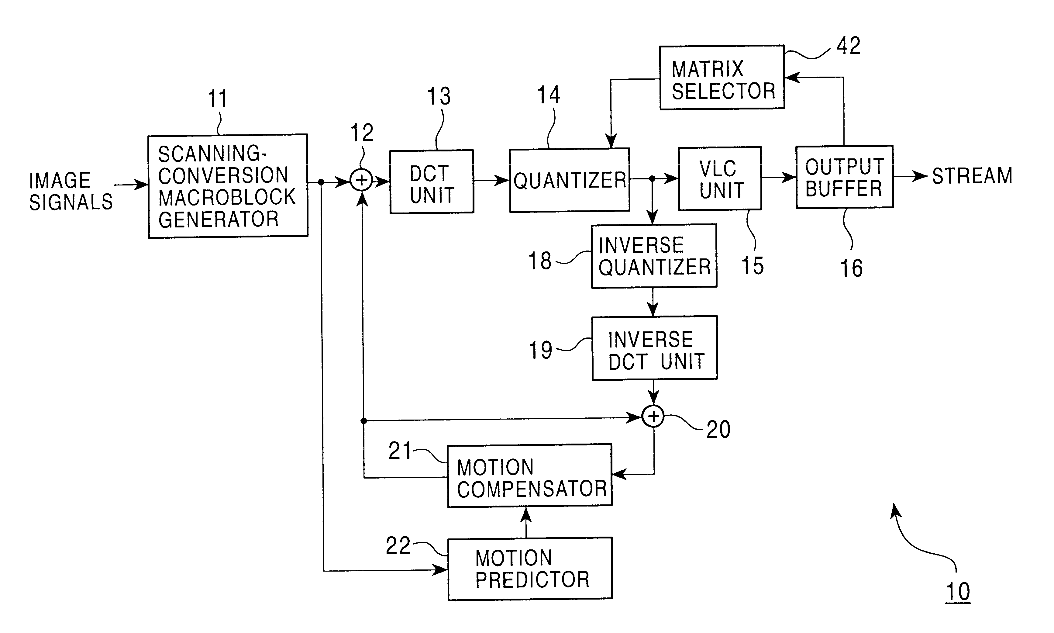
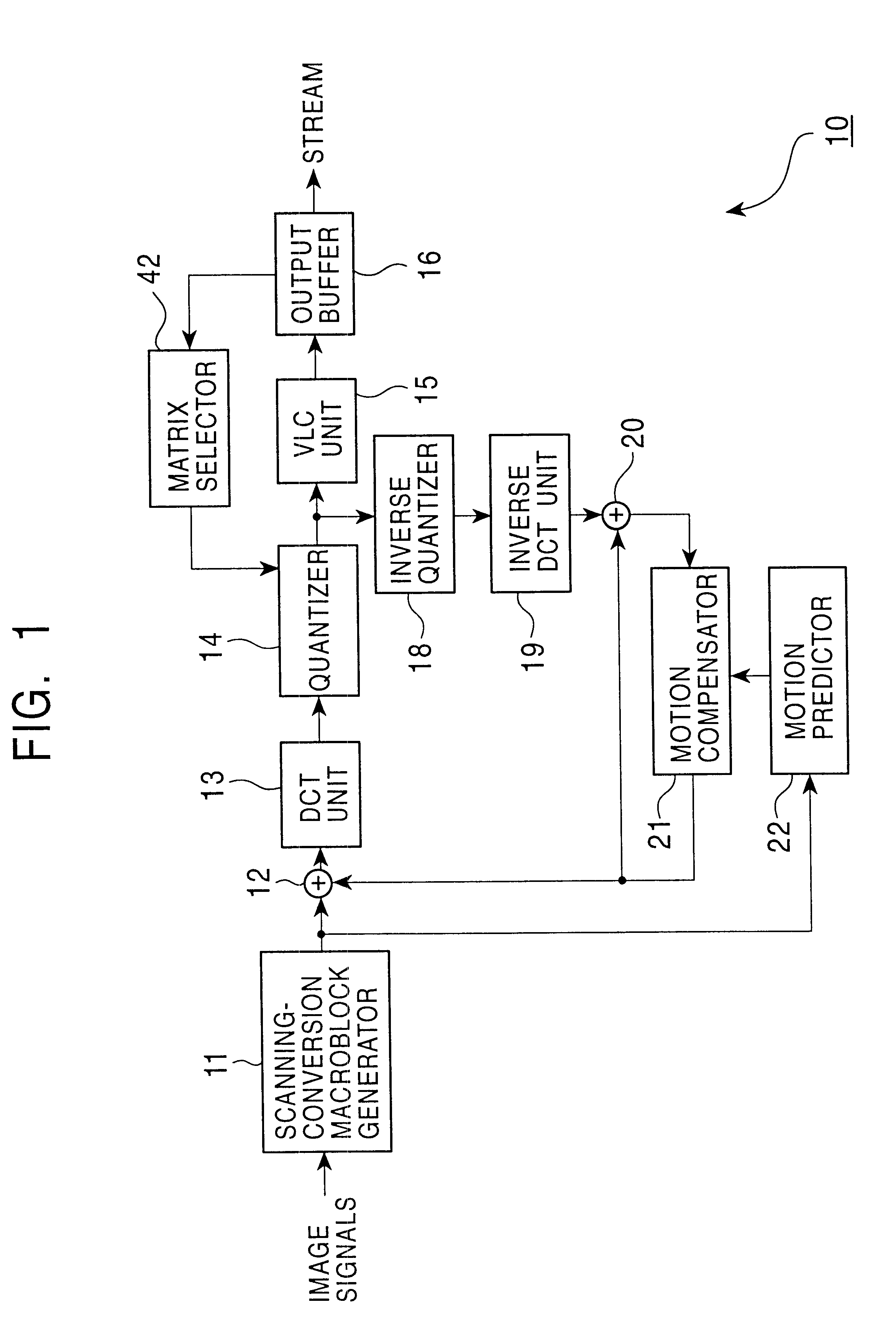
[0051]Referring to the block diagram shown in FIG. 3, an encoder 10 according to an embodiment of the present invention includes a scanning-conversion macroblock generator 11, a DCT unit 13, a quantizer 14, a VLC unit 15, a matrix unit 41, an output buffer 16, a rate controller 17, and a matrix selector 42. Although in the encoder 10 shown in FIG. 3, a motion-compensation control function (the adder 12, the inverse quantizer 18, and the motion compensator 22) as shown in FIG. 1 is omitted for simplicity of description, the encoder 10 shown in FIG. 3 actually has the function.

[0052]The encoder 10 shown in FIG. 3 differs from the encoder shown in FIG. 1 in that the encoder 10 shown in FIG. 3 includes the matrix selector 42, which selects a quantization matrix described in an encoded stream, and the matrix unit 41, which rewrites the quantization matrix, so that a quantization matrix used by the quantizer 14 and a quantization matrix used by the inverse quantizer 33 (shown in FIG. 2) a...


PUM


Abstract

An encoding apparatus and method prevents image deterioration generated by repeatedly performing encoding and decoding by using a quantization matrix for quantization which is different from a quantization matrix for inverse quantization. In the encoding apparatus, a matrix selector selects a first quantization matrix in accordance with the complexity of an encoded picture pattern, and supplies a quantizer with information on the selected first quantization matrix. A matrix unit rewrites, by information on a second quantization matrix, the information described in an encoded stream output from a variable length code unit so that a quantization matrix to be used for inverse quantization is a second quantization matrix different from the first quantization matrix.

Description

BACKGROUND OF THE INVENTION[0001]1. Field of the Invention[0002]The present invention relates to encoding apparatuses and methods for encoding video data, and in particular, to an encoding apparatus and method that uses different quantization matrices for quantization and inverse quantization, whereby, when quantization and inverse quantization are repeatedly performed, image-quality deterioration in video data can be prevented.[0003]2. Description of the Related Art[0004]In the field of video-data recording and reproduction in videocassette recorders and video servers for broadcasting stations and practical use, it has become common, with the establishment of compression encoding based on the moving picture experts group two (MPEG-2) standard, that video data compressed based on the MPEG-2 standard are recorded and reproduced.[0005]FIG. 1 shows the structure of a general encoder 10 that performs compression encoding. As shown in FIG. 1, in an encoder 10, image signals are input to ...

Claims


Application Information

Patent Timeline
Patent Type & Authority Patents(United States)
IPC IPC(8): G06T9/00H04N7/26H04N7/50H04N19/126H04N1/41H04N19/00H04N19/152H04N19/159H04N19/176H04N19/196H04N19/423H04N19/503H04N19/51H04N19/60H04N19/61H04N19/625H04N19/85H04N19/91
CPCH04N19/61H04N19/126
Inventor MIHARA, KANJI
Owner SONY CORP
Why Eureka
Try Eureka