
Fuel injection valve

a fuel injection valve and valve body technology, applied in the direction of fuel injection apparatus, spraying apparatus, charge feed system, etc., can solve the problems of the inability to obtain the atomization enhancement effect of the fuel spray by the cavitation collapse in the fuel jet after injection, and the inability to achieve the atomization enhancement effect of the fuel spray by the cavitation collapse in

Inactive Publication Date: 2010-05-11
TOYOTA CENT RES & DEV LAB INC
View PDF41 Cites 23 Cited by
  • Summary
  • Abstract
  • Description
  • Claims
  • Application Information

AI Technical Summary

Benefits of technology

The present invention provides a fuel injection valve that can enhance atomization in a fuel spray. This is achieved by generating cavitation bubbles in the fuel, storing them in a bubble storage flow path, and then injecting them from the nozzle hole. The cavitation bubbles mix with the fuel to form a mixture of gas and liquid, resulting in improved atomization of the fuel spray. The valve also includes a structure that prevents the bubbles from flowing directly from the cavitation generation flow path to the nozzle hole, which further enhances atomization. Additionally, the valve can include a swirl generation flow path to alleviate non-uniformity in flow rate distribution.

Problems solved by technology

In addition, because a projecting pin is provided inside the nozzle hole, the cavitation bubbles also collapse in the downstream nozzle hole.
Therefore, the atomization enhancement effect of the fuel spray by the cavitation collapse cannot be obtained in the fuel jet after injection.
Because of this, the atomization enhancement effect of the fuel spray by the cavitation collapse cannot be obtained in a wide area in the fuel jet after injection.

Method used


Image

  • Fuel injection valve
  • Fuel injection valve
  • Fuel injection valve

Examples


Embodiment Construction

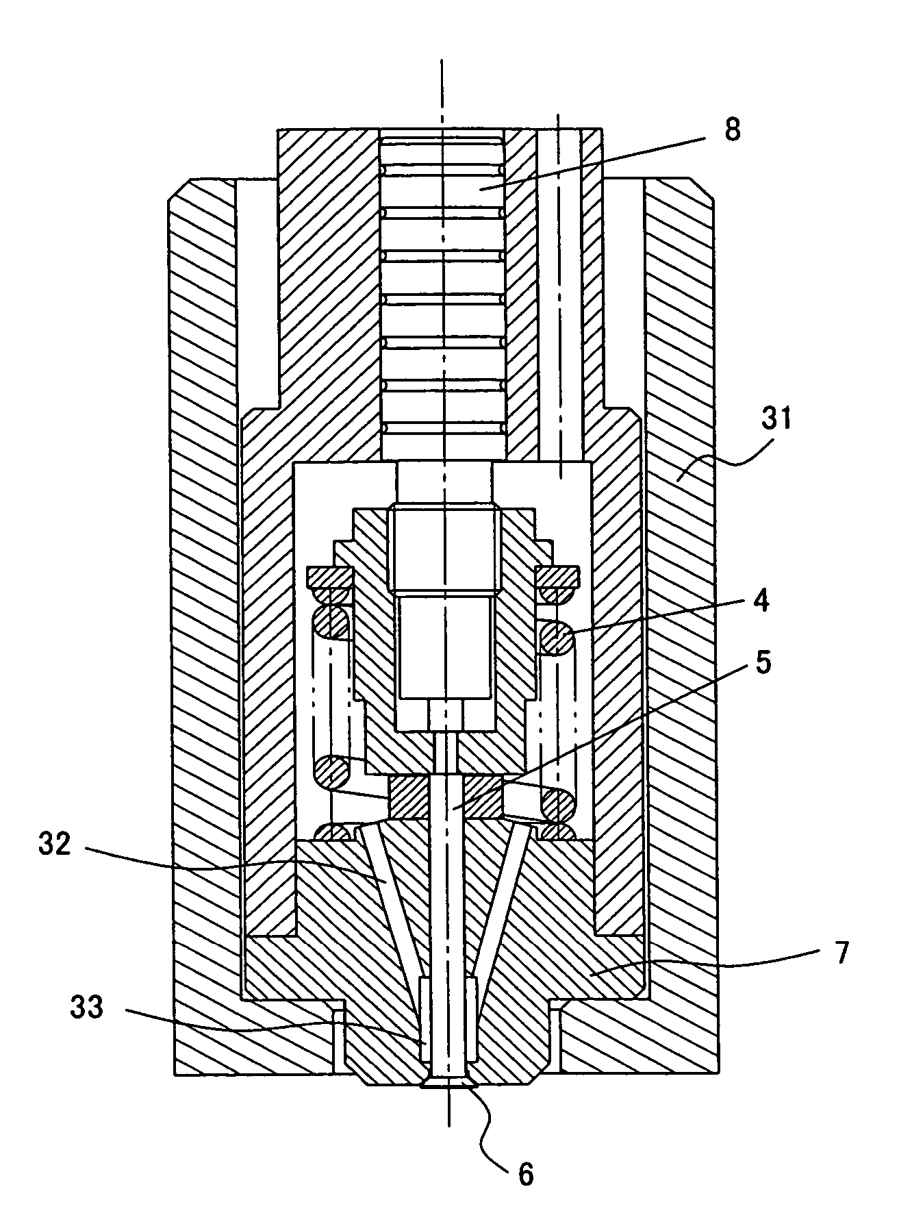
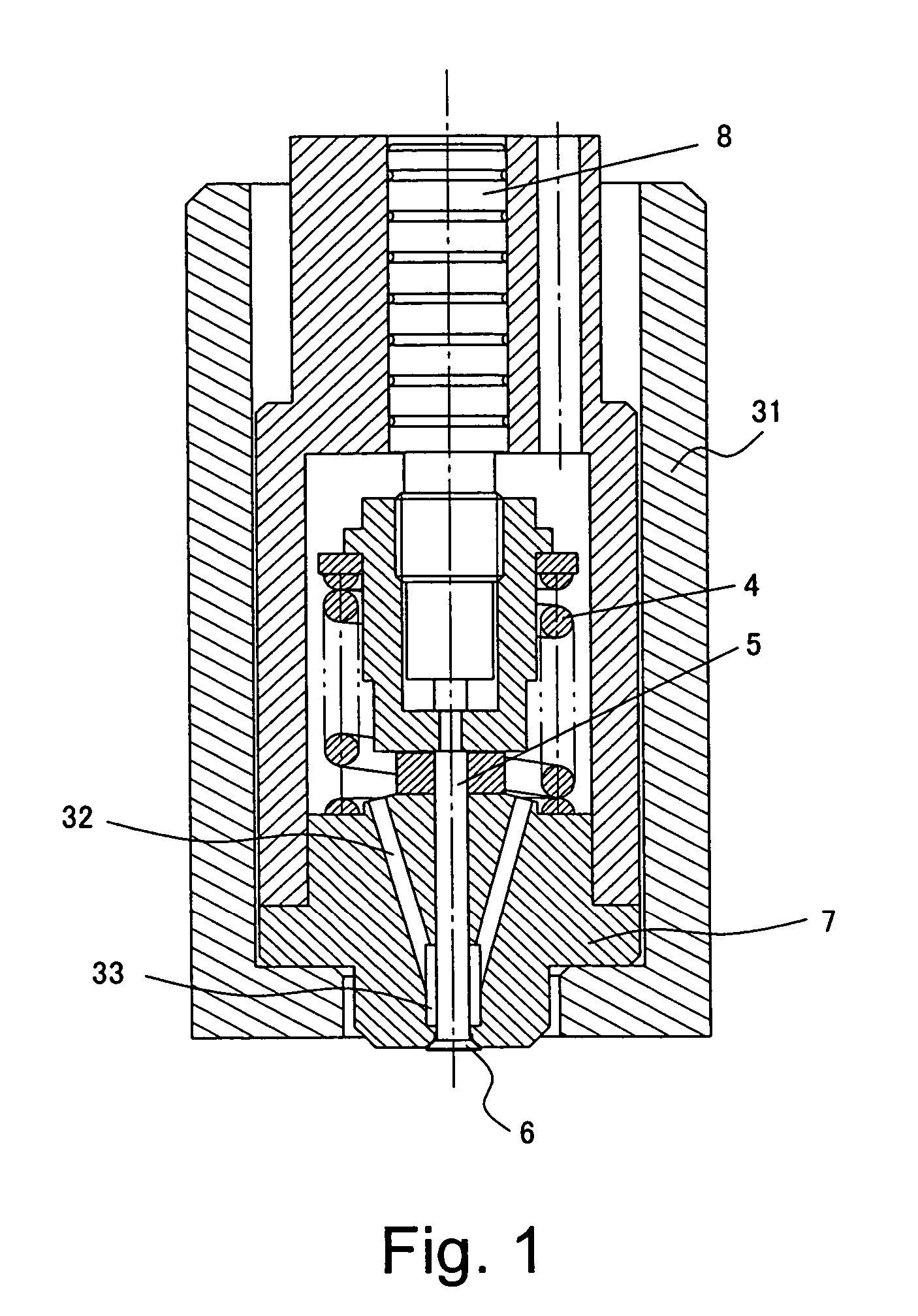
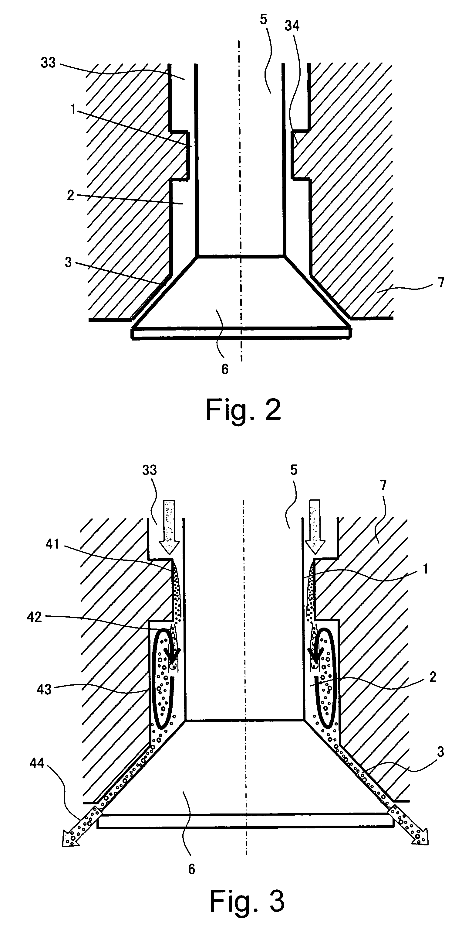
[0062]A preferred embodiment of the present invention will now be described. FIGS. 1 and 2 are diagrams schematically showing a structure of a fuel injection valve according to a preferred embodiment of the present invention. FIG. 1 shows an internal structure of the fuel injection valve and FIG. 2 schematically shows a structure of a tip of a nozzle body. A fuel injection valve of the present embodiment is a fuel injection valve of an externally open valve type and used in, for example, internal combustion engines.

[0063]A nozzle body 7 is provided inside a valve housing 31. A nozzle hole 3 is formed on a tip of the nozzle body 7. A pintle 5 is inserted in a hollow portion formed in the central portion of the nozzle body 7 and is supported in a slidable state along an inner peripheral surface of the nozzle body 7. One end of the pintle 5 is connected to a plunger 8 and a poppet valve 6 is provided on the other end of the pintle 5. A biasing force toward the plunger 8 (toward the top...


PUM


Abstract

A fuel injection valve which injects fuel from a nozzle hole includes a cavitation generation flow path in which a cavitation bubble is generated in fuel flowing inside the injection valve, and a bubble storage flow path which is connected to the cavitation generation flow path and the nozzle hole and which stores the cavitation bubble generated in the cavitation generation flow path. A fuel containing the cavitation bubble stored in the bubble storage flow path is injected from the nozzle hole so that atomization of an injected fuel spray is enhanced.

Description

[0001]The entire disclosure of Japanese Patent Application No. 2004-368558 including specification, claims, drawings and abstract is incorporated herein by reference.BACKGROUND OF THE INVENTION[0002]1. Field of the Invention[0003]The present invention relates to a fuel injection valve which injects a fuel from a nozzle hole, and more particularly to a fuel injection valve which generates a cavitation bubble in fuel flowing inside an injection valve.[0004]2. Description of the Related Art[0005]Fuel injection valves which generate cavitation bubbles in fuel flowing inside an injection valve in order to enhance atomization in a fuel spray have been proposed. Japanese Patent Laid-Open Publication No. 2003-83205, Japanese Patent Laid-Open Publication No. 2004-19481, and N. Tamaki et al., “Atomization Enhancement of the Spray and Improvement of the Spray Characteristics by Cavitation and Pin Inserted in the Nozzle Hole”, ICLASS, 2003 describe related art of such a structure. The fuel inje...

Claims


Application Information

Patent Timeline
Patent Type & Authority Patents(United States)
IPC IPC(8): F02M61/00B05B1/14F02M61/10F02M61/08B05B1/26B05B1/32
CPCF02M61/08F02M61/12F02M61/186F02M61/1853F02M61/162
Inventor MASUDA, RYOKAWAMURA, KIYOMINAGAOKA, MAKOTO
Owner TOYOTA CENT RES & DEV LAB INC
Learn More