Luminance enhancement optical substrates with anti-chatter structures

a technology of optical substrates and structures, applied in the direction of instruments, lighting and heating apparatus, mechanical apparatus, etc., can solve the problems of affecting the integration of adhesion, undesirable bright lines artifacts in the display image, so as to enhance luminance or brightness and reduce the effect of chatter

Active Publication Date: 2010-05-11
UBRIGHT OPTRONICS CORP
View PDF49 Cites 13 Cited by
  • Summary
  • Abstract
  • Description
  • Claims
  • Application Information

AI Technical Summary

Benefits of technology

[0012]The present invention is directed to an optical substrate that possesses a structured surface that enhances luminance or brightness and reduces chatter phenomenon. In accordance with the present invention, anti-chatter is achieved by providing a structured surface in which the bottoms of some of the valleys of longitudinal prisms are coplanar to the surface of the underlying support or base layer. All the valleys do not lie in the same plane in the inventive structure. In one embodiment, the distance between the valleys to the support layer remains substantially similar for a first number of adjacent valleys, but is substantially zero for a second number of adjacent valleys after every n-th adjacent valleys, wherein the first number and second number of adjacent valleys are non-zero.

Problems solved by technology

The integrity of the adhesion is affected by environmental conditions, such as moisture and heat.
For example, when the brightness enhancement film 100 is subject to moisture and high temperature, the structured layer 104 could separate from the base layer 102, which separation between the layer would result in artifacts in the display image, such as undesirable bright lines in the display image.
However, it is challenging to control a consistent bottom thickness d. Alignment errors could be introduced by the mechanical system used to form the structured surface.
For example, dynamic mechanical alignment errors from the master roll and curing machine are on an order comparable or larger than the bottom thickness d. As a result, those factors would introduce some unwanted cosmetic defects such as ‘chatter’ and / or non-uniformity of the brightness enhancement film.

Method used


Image

  • Luminance enhancement optical substrates with anti-chatter structures
  • Luminance enhancement optical substrates with anti-chatter structures
  • Luminance enhancement optical substrates with anti-chatter structures

Examples


Embodiment Construction

[0020]The present description is of the best presently contemplated mode of carrying out the invention. This invention has been described herein in reference to various embodiments and drawings. This description is made for the purpose of illustrating the general principles of the invention and should not be taken in a limiting sense. It will be appreciated by those skilled in the art that variations and improvements may be accomplished in view of these teachings without deviating from the scope and spirit of the invention. The scope of the invention is best determined by reference to the appended claims.

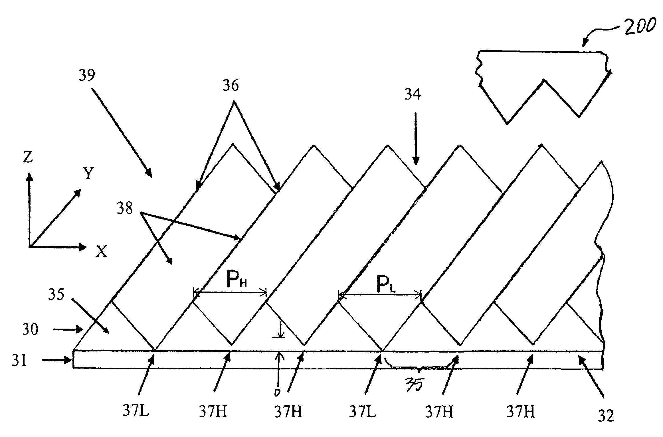
[0021]The present invention is directed to an optical substrate that possesses a structured surface that enhances brightness. In one aspect of the present invention, the optical substrate is in the form of a film, sheet, plate, and the like, which may be flexible or rigid, having a three-dimensionally varying, structured light output surface that comprises a prism structure, and a n...


PUM


Abstract

An optical substrate possesses a structured surface that enhances luminance or brightness and reduces chatter phenomenon. A structured surface is provided, in which some of the valleys (low valleys) are coplanar to the surface of the underlying support layer and other valleys (high valleys) are not coplanar on the support layer. The low valleys have bottom thickness that is substantially smaller than that of the high valleys. The distance from the valleys to the support layer remains substantially similar for a first number of adjacent valleys, but is substantially zero for a second number of adjacent valleys after every n-th adjacent valleys.

Description

[0001]This application claims the priority of U.S. Provisional Application No. 60 / 742,959, filed Dec. 6, 2005.This document is fully incorporated by reference as if fully set forth herein.[0002]The publications noted in the disclosure herein are each fully incorporated by reference, as if fully set forth in its entirety herein.BACKGROUND OF THE INVENTION[0003]1. Field of the Invention[0004]The present invention relates to optical substrates having a structured surface, particularly to optical substrates for brightness enhancement, and more particularly to brightness enhancement substrates for use in flat panel displays having a planar light source.[0005]2. Description of Related Art[0006]Flat panel display technology is commonly used in television displays, computer displays, and handheld electronics (e.g., cellular phones, personal digital assistants (PDAs), etc.). Liquid crystal display (LCD) is a type of flat panel display, which deploys a liquid crystal (LC) module having an arr...

Claims


Application Information

Patent Timeline
Patent Type & Authority Patents(United States)
IPC IPC(8): F21V8/00
CPCG02B5/04G02F1/133615G02B6/0053G02B6/0046G02F1/133606
Inventor WANG, KONG-HUALIN, CRAIGKO, DANIEL YAW-CHUNG
Owner UBRIGHT OPTRONICS CORP
Why Eureka
Try Eureka