Battery module and middle or large-sized battery pack containing the same

a battery module and battery pack technology, applied in the field of batteries, can solve the problems of increasing the total size of the system, affecting the work efficiency of the battery module, so as to improve the work efficiency, and reduce the volume of the battery module

Active Publication Date: 2010-05-11
LG ENERGY SOLUTION LTD
View PDF7 Cites 29 Cited by
  • Summary
  • Abstract
  • Description
  • Claims
  • Application Information

AI Technical Summary

Benefits of technology

[0011]Specifically, it is an object of the present invention to provide a battery module having a compact structure in which the battery module is stably mounted in a limited space, such as a vehicle, and that is easily assembled and disassembled, thereby improving the work efficiency, and a middle- or large-sized battery pack including the same.
[0029]The middle- or large-sized battery pack according to the present invention may be used as a power source for electric vehicles, hybrid electric vehicles, uninterruptible power supplies (UPS), idle reduction devices, and energy storage devices, which have a limited installation space and are exposed to frequent vibration and strong impact, in consideration of the installation efficiency and structural stability of the battery pack. Especially, the middle- or large-sized battery pack according to the present invention is preferably used as a charging and discharging power source for electric vehicles.

Problems solved by technology

Consequently, when a middle- or large-sized battery module is constructed using a plurality of battery cells, a plurality of members for mechanical coupling and electrical connection between the battery cells are generally needed, and, as a result, a process for assembling the mechanical coupling and electrical connection members is very complicated.
Furthermore, there is needed a space for coupling, welding, or soldering the mechanical coupling and electrical connection members, with the result that the total size of the system is increased.
In addition, when some of the battery modules, constituting the middle- or large-sized battery module, are abnormally operated, it takes a large amount of time and a large number of processes during the disassembly and assembly of the battery modules to replace the abnormally operated battery modules with new ones.

Method used


Image

  • Battery module and middle or large-sized battery pack containing the same
  • Battery module and middle or large-sized battery pack containing the same
  • Battery module and middle or large-sized battery pack containing the same

Examples


Embodiment Construction

[0038]Now, preferred embodiments of the present invention will be described in detail with reference to the accompanying drawings. It should be noted, however, that the scope of the present invention is not limited by the illustrated embodiments.

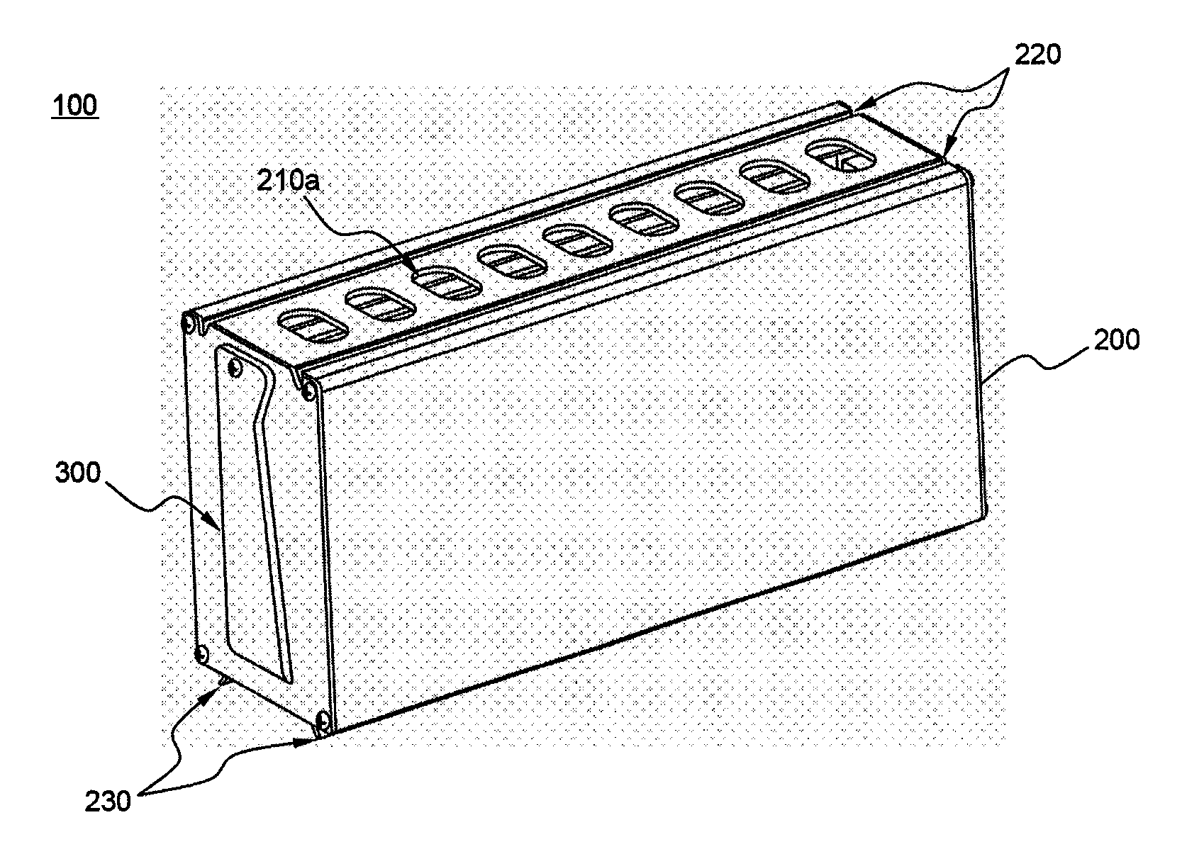
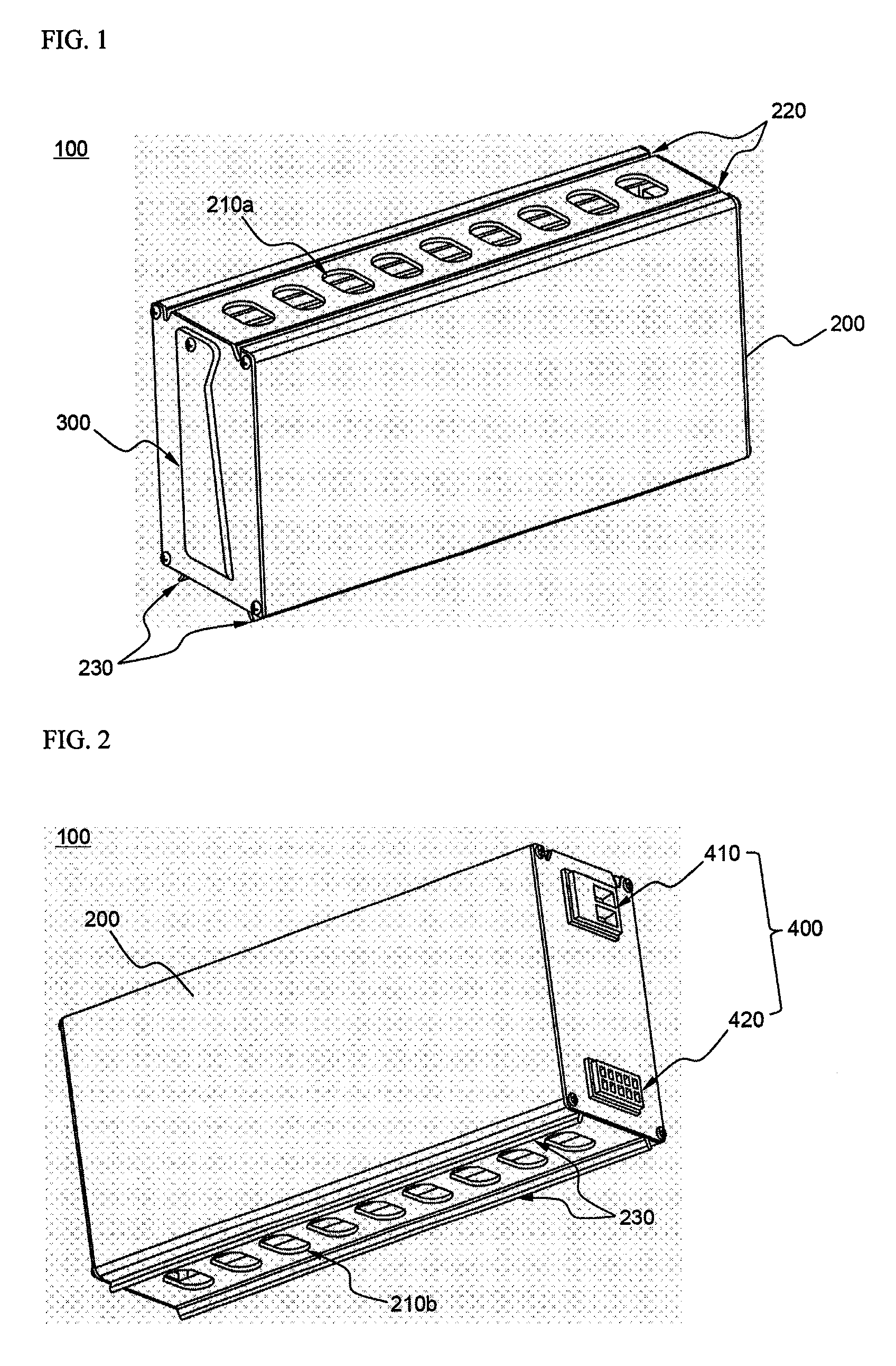
[0039]FIGS. 1 and 2 are perspective views typically illustrating the front and rear of a battery module according to a preferred embodiment of the present invention, respectively.

[0040]Referring first to FIG. 1, a module case 200 is mounted to the outside of the battery module 100. At the middle of the top of the module case 200 are formed a plurality of through-holes 210a for cooling battery cells of the battery module 100. At the right and left sides of the through-holes 210a are formed sliding grooves 220, which extend in the longitudinal direction of the module case 200. At the bottom of the module case 200 are formed sliding protrusions 230 corresponding to the sliding grooves 220. Consequently, when battery modules 100 are stacked in t...


PUM

PropertyMeasurementUnit
heightaaaaaaaaaa
widthaaaaaaaaaa
densityaaaaaaaaaa

Abstract

Disclosed herein is a battery module constructed in a structure in which a cell stack, including a plurality of secondary battery cells (‘battery cells’) or a plurality of unit modules, each of which including a plurality of battery cells, stacked with high density, is mounted in a hexahedral module case, wherein the module case is provided at least one side thereof with a sliding coupling structure, and the battery module has a variable grip mounted thereto.

Description

CROSS REFERENCE TO RELATED APPLICATIONS[0001]The present application is a national phase entry under 35 U.S.C. §371 of International Application No. PCT / KR2007 / 004294, filed Sep. 6, 2007, published in English, which claims the benefit of Korean Patent Application No. 10-2006-0089897, filed Sep. 18, 2006. The disclosures of said applications are incorporated by reference herein.FIELD OF THE INVENTION[0002]The present invention relates to a battery module having a specific structure and a battery pack including a plurality of such battery modules, and, more particularly, to a battery module constructed in a structure in which a cell stack, including a plurality of secondary battery cells (‘battery cells’) or a plurality of unit modules, each of which including a plurality of battery cells, stacked with high density, is mounted in a hexahedral module case, wherein the module case is provided at least one side thereof with a sliding coupling structure, and the battery module has a varia...

Claims


Application Information

Patent Timeline
Patent Type & Authority Patents(United States)
IPC IPC(8): H01M2/10H01M2/04H01M6/46H01M50/105H01M50/119H01M50/121H01M50/124H01M50/211H01M50/224H01M50/262H01M50/296
CPCH01M2/0207H01M2/0245H01M2/0272H01M2/0275H01M10/5067H01M2/1077H01M10/5004H01M2/1005H01M10/5032H01M10/6563H01M10/647H01M10/613Y02E60/10H01M50/258H01M50/1243H01M50/256H01M50/224H01M50/105H01M50/121H01M50/124H01M50/296H01M50/262H01M50/211H01M50/119H01M50/20H01M50/10
Inventor HA, JIN WOONGKIM, JEEHOSHIN, YONGSHIK
Owner LG ENERGY SOLUTION LTD
Why Eureka
Try Eureka