Gait generating device of mobile robot

a technology of generating device and robot, which is applied in the direction of electric programme control, program control, instruments, etc., can solve the problem of frequent changes in the posture of the predetermined part in the first provisional correction instantaneous desired motion, and achieve the effect of improving dynamic accuracy, and reducing the risk of injury

Inactive Publication Date: 2010-05-11
HONDA MOTOR CO LTD
View PDF26 Cites 5 Cited by
  • Summary
  • Abstract
  • Description
  • Claims
  • Application Information

AI Technical Summary

Benefits of technology

[0014]According to the first invention, properly setting the first geometric restrictive condition and the second geometric restrictive condition and also properly setting the elements constituting the model make it possible to match the difference between the second placement and the first placement (the difference between the placement of the elements in the second placement and the placement of the elements in the first placement) to the level (degree) of the dynamic error between the first provisional corrected instantaneous desired motion (the instantaneous desired value of at least one of the position and the posture of each part of the robot determined by the first provisional corrected instantaneous desired motion) and an instantaneous desired floor reaction force generated by the instantaneous gait generating means (the instantaneous desired value of at least one of the translational force of a floor reaction force and a moment acting on the robot). Similarly, it is possible to match the difference between the third placement and the first placement (the difference between the placement of the elements in the third placement and the placement of the elements in the first placement) to the level (degree) of the dynamic error between the second provisional corrected instantaneous desired motion (the instantaneous desired value of at least one of the position and the posture of each part of the robot determined by the second provisional corrected instantaneous desired motion) and an instantaneous desired floor reaction force generated by the instantaneous gait generating means. Supplementally, this matching relationship generally involves a steady offset.
[0344]As explained above, the present invention is useful in that it makes it possible to provide a gait generating device of a mobile robot that is capable of properly correcting a motion of an instantaneous desired gait, which is prepared using a dynamic model, by geometric computation that does not include differential equations or integral equations, thus achieving improved dynamic accuracy of the instantaneous desired gait that includes the corrected motion, while minimizing a change in the posture of a predetermined part, such as the body of the robot, at the same time.

Problems solved by technology

However, there is a danger in that the posture of the predetermined part in the first provisional corrected instantaneous desired motion frequently changes.

Method used


Image

  • Gait generating device of mobile robot
  • Gait generating device of mobile robot
  • Gait generating device of mobile robot

Examples


first embodiment

[0115]A first embodiment in accordance with the present invention will now be specifically explained. First, the simplified model (dynamic model), the first displacement dimension correcting model, and the second displacement dimension correcting model in the first embodiment will be explained. Incidentally, the first embodiment is an embodiment according to the first, the third, the fourth, the seventh to the ninth, and the eleventh to the fourteenth inventions mentioned above.

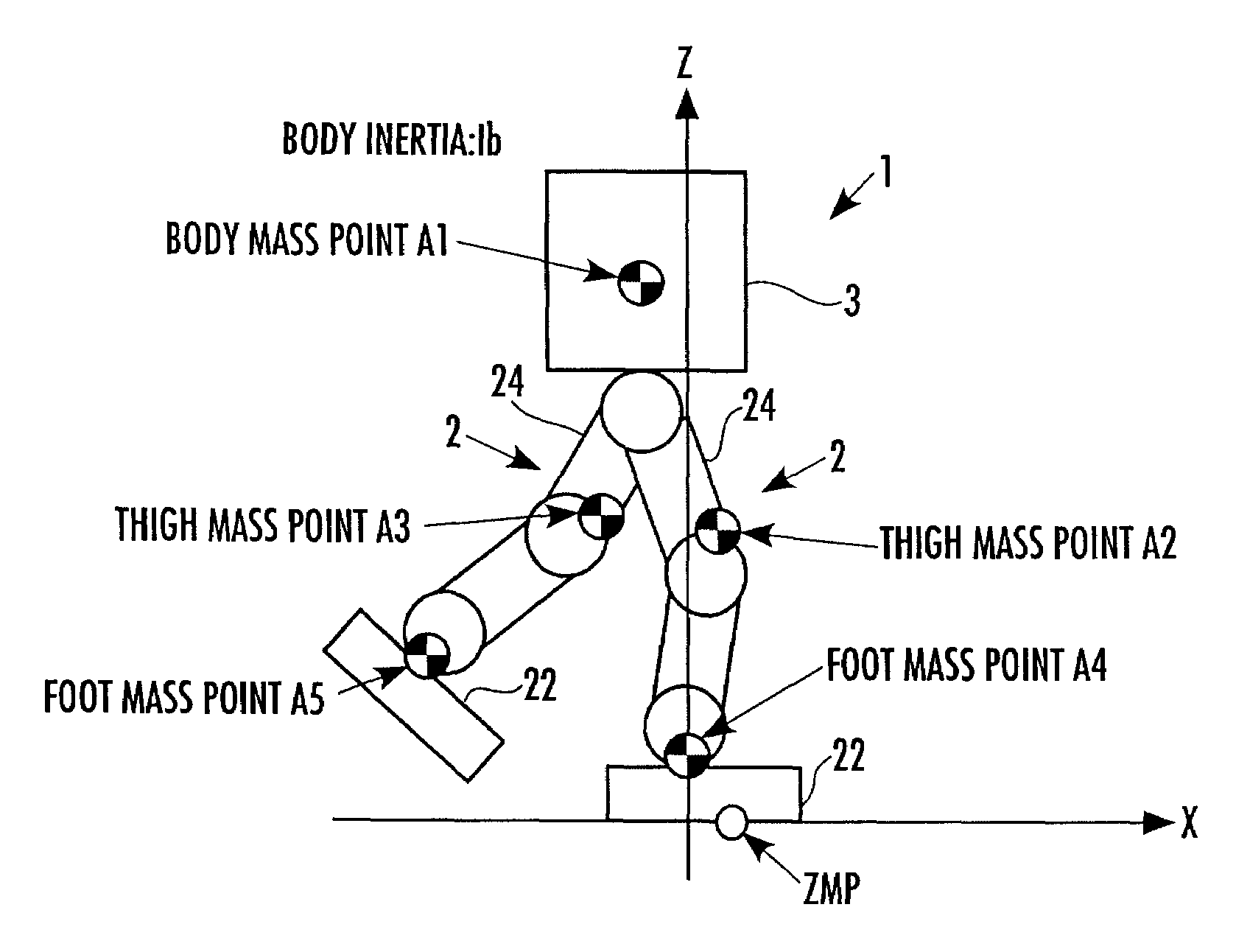
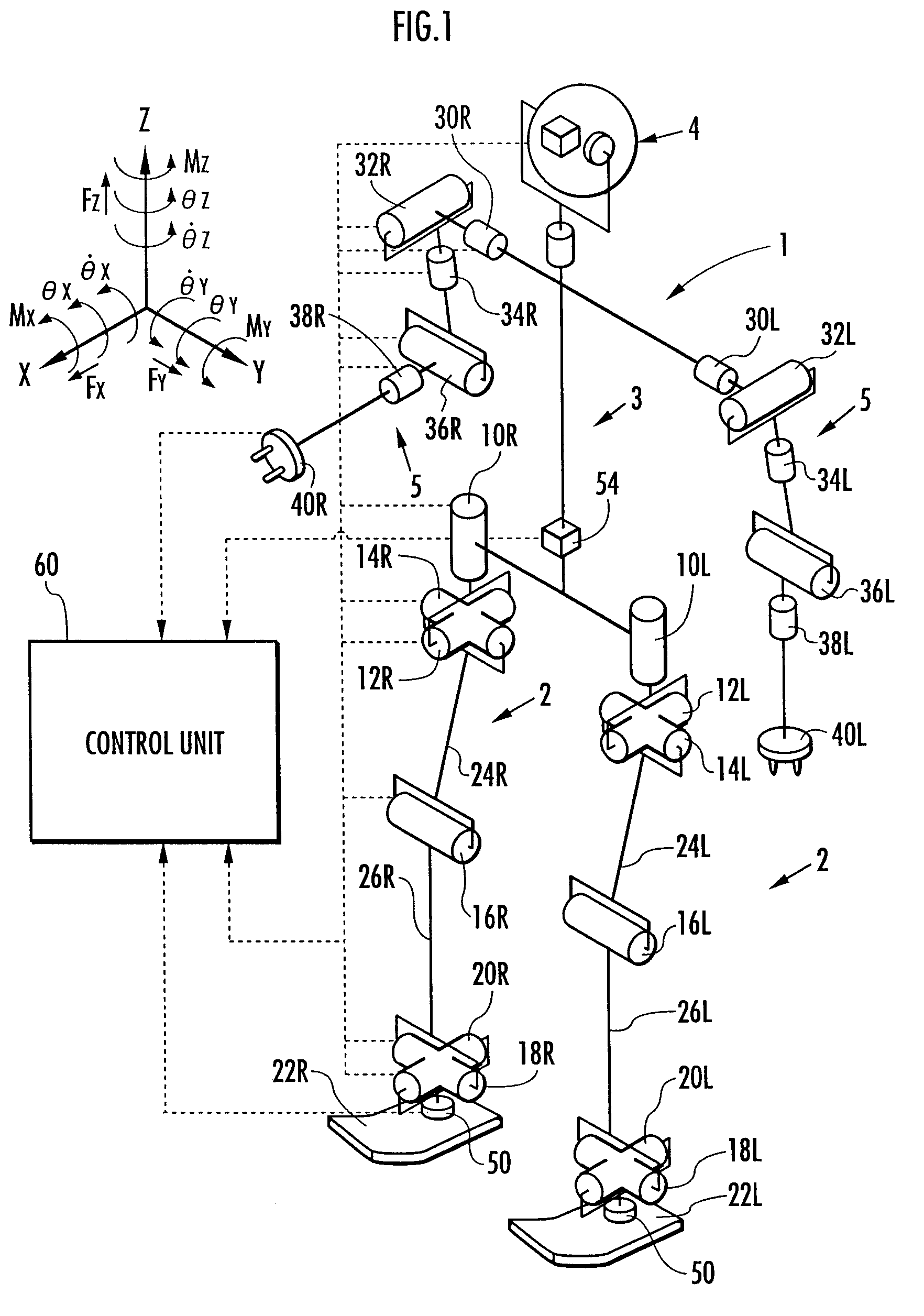
[0116]FIG. 6 shows the structure of a simplified model in the first embodiment. As illustrated, the simplified model is a one-mass-point model equipped with one mass point (body mass point) 3m corresponding to a body 3 of a robot 1. The robot 1 shown in FIG. 6 is the robot 1 schematically side-viewed, arms 5, 5 and a head 6 being omitted. In the figures following FIG. 6 (including the drawings of embodiments other than the first embodiment), when illustrating the robot 1, the arms 5, 5 and the head 6 will be ...

second embodiment

[0245]A second embodiment in accordance with the present invention will now be explained with reference to FIG. 18 to FIG. 22. In the present embodiment, the constructions of a robot 1 and a control unit 60 are the same as those in the first embodiment, whereas a simplified model, a first displacement dimension correcting model, and a part of the processing of a gait generating device 100 are different from those of the first embodiment. Hence, in the explanation of the present embodiment, the same reference numerals and drawings as those in the first embodiment will be used for the same parts as those in the first embodiment, and detailed explanation thereof will be omitted. The second embodiment represents an embodiment of the first, the third, the fourth, the seventh to the tenth, and the thirteenth to the fifteenth inventions of the present invention.

[0246]FIG. 19 shows a structure of a simplified model (dynamic model) in the present embodiment, and FIG. 18 shows a structure of ...

third embodiment

[0298]A third embodiment of the present invention will now be explained with reference to FIG. 23 to FIG. 25. The present embodiment shares the same construction of the robot 1 as that of the first and the second embodiments, and also shares the same structures of a simplified model, a first displacement dimension correcting model and a second displacement dimension correcting model as those of the second embodiment. And, the present embodiment differs from the second embodiment only in a part of the processing of a gait generating device 100. Hence, in the explanation of the present embodiment, the same reference numerals and drawings as those of the second embodiment will be used for the same portions as those of the second embodiment, and detailed explanation will be omitted. The following will explain the present embodiment, focusing mainly on the portions that are different from those of the second embodiment. Incidentally, the present embodiment is an embodiment of the second ...


PUM


Abstract

The placement of the elements (mass points or rigid bodies having inertia) of a model expressing a robot 1 determined according to a first geometric restrictive condition from an instantaneous desired motion of the robot 1 is defined as a first placement, and provisional corrected instantaneous desired motions corresponding to a second placement and a third placement having predetermined relationships with the first placement are determined. The position / posture of a predetermined part 3 (body) of the robot 1 are determined by weighted averages of the position / posture of the aforesaid provisional corrected instantaneous desired motions. Thus, the motion of an instantaneous desired gait created using a dynamic model is properly corrected thereby achieving both improved dynamic accuracy between the motion and a floor reaction force of the instantaneous desired gait and a minimized change in the posture of a predetermined part, such as the body, of the robot without using a dynamic model.

Description

TECHNICAL FIELD[0001]The present invention relates to a device for generating desired gaits of a mobile robot, such as a bipedal mobile robot.BACKGROUND ART[0002]As techniques for generating desired gaits of a mobile robot, such as a bipedal mobile robot, one disclosed in, for example, Japanese Unexamined Patent Application Publication No. 2002-326173 (patent document 1) and one disclosed in PCT international publication WO / 03 / 057427 / A1 (patent document 2) have been proposed by the present applicant. According to the techniques disclosed in these documents, an instantaneous desired gait composed of an instantaneous value of a desired motion (instantaneous desired motion) of a robot and an instantaneous value of a desired floor reaction force (instantaneous desired floor reaction force) is sequentially created using a first dynamic model representing a relationship between a motion of the robot (the position and the posture of each part) and a floor reaction force such that a require...

Claims


Application Information

Patent Timeline
Patent Type & Authority Patents(United States)
IPC IPC(8): G06F19/00B25J5/00B25J13/00B62D57/032
CPCB62D57/032B25J5/00B25J13/00
Inventor TAKENAKA, TORUMATSUMOTO, TAKASHIYOSHIIKE, TAKAHIDE
Owner HONDA MOTOR CO LTD
Why Eureka
Try Eureka