Floor cleaning machine

Inactive Publication Date: 2010-05-18
CFM NILFISK ADVANCE
View PDF2 Cites 6 Cited by
  • Summary
  • Abstract
  • Description
  • Claims
  • Application Information

AI Technical Summary

Benefits of technology

[0020]It is therefore a main object of the present invention to provide a floor-cleaning machine that is provided with a front flap that does away with the afore-cited drawbacks of prior-art equipment.
[0021]Within this general object, it is a purpose of the present invention to provide a front flap that is more versatile and practical than the front flaps currently available on the market, and is capable of being used so as to selectively favor the suction capacity or a reduced noise level of the machine, in accordance with the requirements of the user.
[0022]A further purpose of the present invention is to provide a flap that is simple in its construction and reliable in use, as well as capable of being manufactured at fully competitive costs.

Problems solved by technology

While seeping through such indentations or cuts, the air and the liquid generate some noise.
Now, the speed of the air being sucked in through the indentations is higher and, as a result, the negative pressure inside the suction chamber is greater, so the noise generated is higher.
It may of course be quite readily appreciated that such tampering is quite difficult job, and further requires a lot of time to be completed, since it involves the front flap to be removed from the wiping device, the additional aperture or apertures to be cut thereinto, and finally the re-processed front flap to be assembled again on to the wiping device.
It can further be readily appreciated that—during the process of making such additional apertures in the front flap, i.e. a process that largely depends on the skills and the experience of the user carrying it out—the front flap may itself be caused—owing to errors in tampering therewith or similar problems—to undergo tears and similar damages that might even impair the good state and operativeness thereof, up to making it necessary for it to be totally replaced.

Method used


Image

  • Floor cleaning machine
  • Floor cleaning machine
  • Floor cleaning machine

Examples


Embodiment Construction

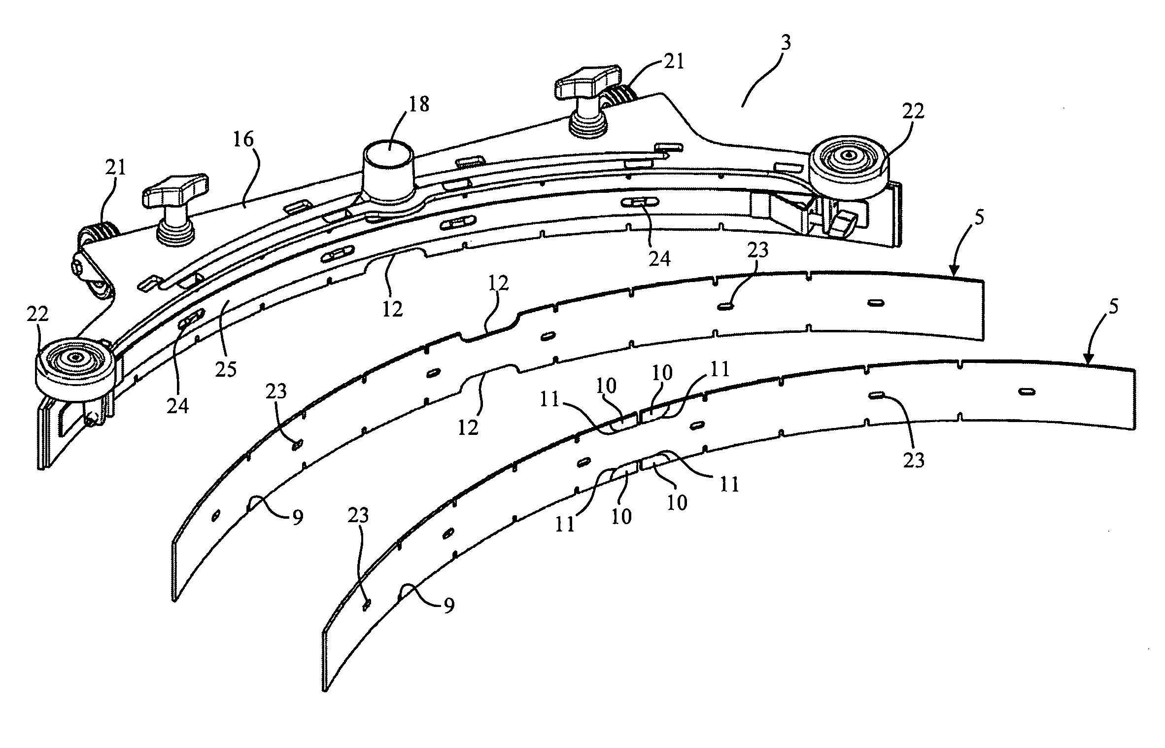
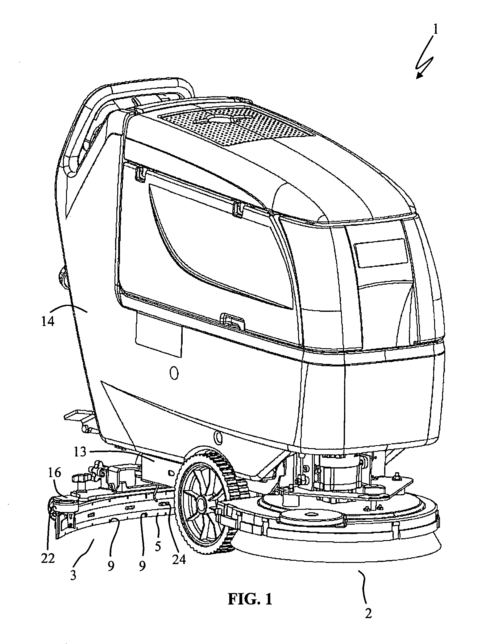
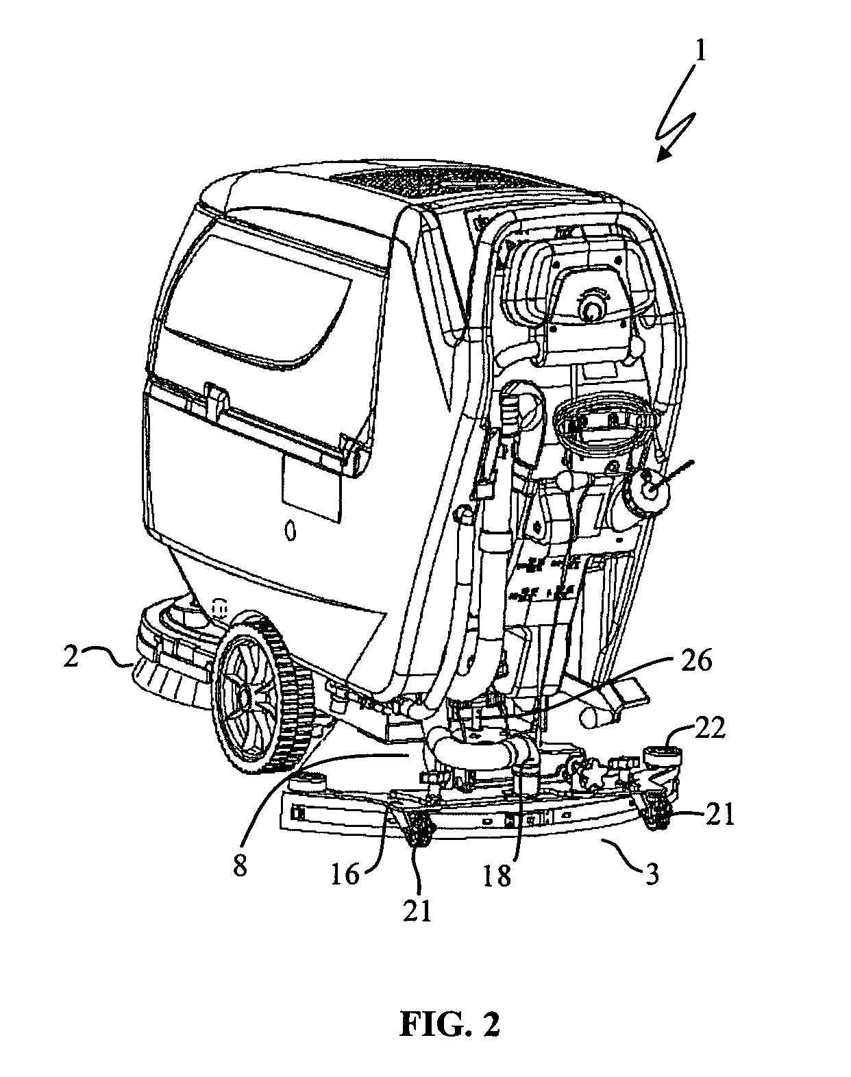
[0032]With reference to the above-noted Figures, the floor cleaning machine according to the present invention, as generally indicated with the reference numeral 1, comprises brush means or unit 2 adapted to scrub the floor 4 with a cleaning, i.e. detergent liquid in view of removing soil and dirt therefrom, and a wiping device 3 adapted to scrape the floor 4 in order to remove the dirty cleaning liquid therefrom.

[0033]The wiping device 3 comprises a front flap 5 and a rear flap 6 adapted to elastically and slidably engage the floor 4 to define a suction chamber 7 therebetween, wherein said suction chamber is fluidly connected to suction means 8. In addition, the front flap 5 is provided with a plurality of indentations 9 of a reduced cross-sectional size to convey the dirty cleaning liquid into the suction chamber 7.

[0034]Advantageously, at least a portion of the front flap 5 is provided in the form of a tab 10 that is associated to the same front flap via a rupture edge 11. Such t...


PUM


Abstract

The present invention refers to a floor cleaning machine comprising a brush adapted to scrub the floor with a cleaning, i.e. detergent, liquid in view of removing soil and dirt therefrom, and a wiping device adapted to scrape the floor in order to remove the dirty cleaning liquid therefrom; the wiping device comprises a front flap and a rear flap adapted to elastically and slidably engage the floor so as to define a suction chamber therebetween, wherein the suction chamber is fluidly connected to a suction device, and wherein the front flap is provided with a plurality of indentations of a reduced cross-sectional size to convey the dirty cleaning liquid into the suction chamber; at least a portion of the front flap is provided in the form of a tab that is associated to the same front flap via a rupture edge, wherein such tab is adapted to be removed so as to form a breach or passageway having a broader cross-sectional size in the front flap in order to reduce the speed of the air entering the suction chamber and, as a result, the related suction noise.

Description

BACKGROUND OF THE INVENTION[0001]I. The Field of Invention[0002]The present invention relates to a floor cleaning machine.[0003]II. Description of Related Art[0004]Floor cleaning devices, i.e. washing-drying machines, usually comprise a brushing device with water and / or a liquid detergent dispensing provision to wash the floor, as well as a wiping device to remove the dirty liquid from the floor and dry up the latter.[0005]Such a wiping device has the purpose of scraping and vacuuming the floor behind the brushing device, in order to remove the dirty liquid therefrom by taking it in through a suction means, with which it is appropriately connected.[0006]The wiping device is usually comprised of a support, to which there are mounted two flaps (or wiping blades, as they are generally referred to in the art) that are made of a rubber-based or rubber-like material to be able to elastically and slidably engage the floor to be cleaned. These flaps, i.e. a front one—facing forwards, i.e. i...

Claims


Application Information

Patent Timeline
IPC IPC(8): A47L9/06A47L1/06A47L5/00A47L7/00A47L9/02E01H1/08
CPCA47L11/30A47L11/4097A47L11/4044Y10T29/49
Inventor COCCAPANI, SERGIOMARCHETTI, FILIPPO
Owner CFM NILFISK ADVANCE
Why Eureka
Try Eureka