Method and apparatus for cooling electronic components

Inactive Publication Date: 2010-05-18
AMAZON TECH INC
View PDF23 Cites 42 Cited by
  • Summary
  • Abstract
  • Description
  • Claims
  • Application Information

AI Technical Summary

Benefits of technology

[0004]In one aspect, a method of cooling at least one electronic component that is configured to generate a predetermined waste heat is provided. The method includes providing a first fluid channeling sub-system that has a first fluid source and at least one controller. The method also

Problems solved by technology

Moreover, some known data centers include a plurality of racking systems that have a plurality of configurations that are non-uniform with respect to component density and usage such that each racking system generates waste heat at a non-uniform ra

Method used


Image

  • Method and apparatus for cooling electronic components
  • Method and apparatus for cooling electronic components
  • Method and apparatus for cooling electronic components

Examples


Embodiment Construction

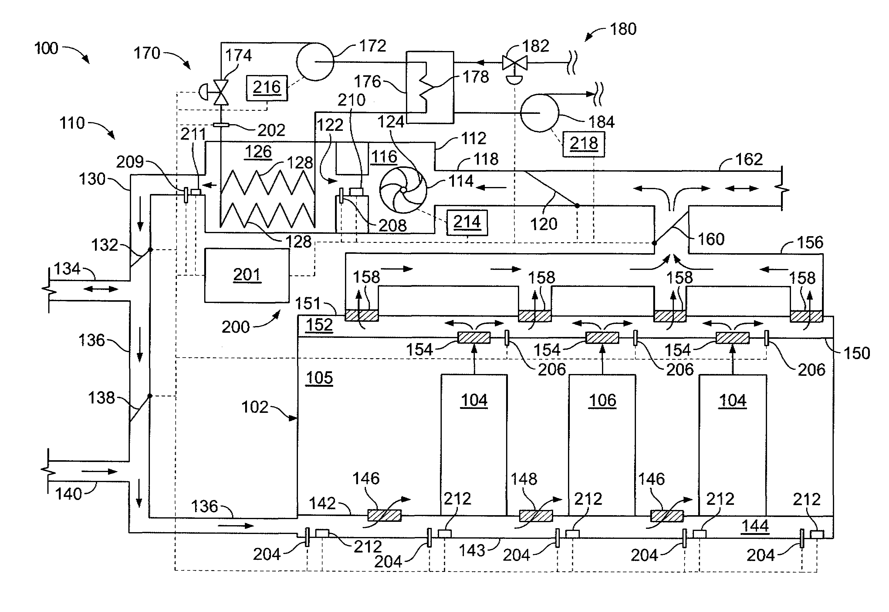
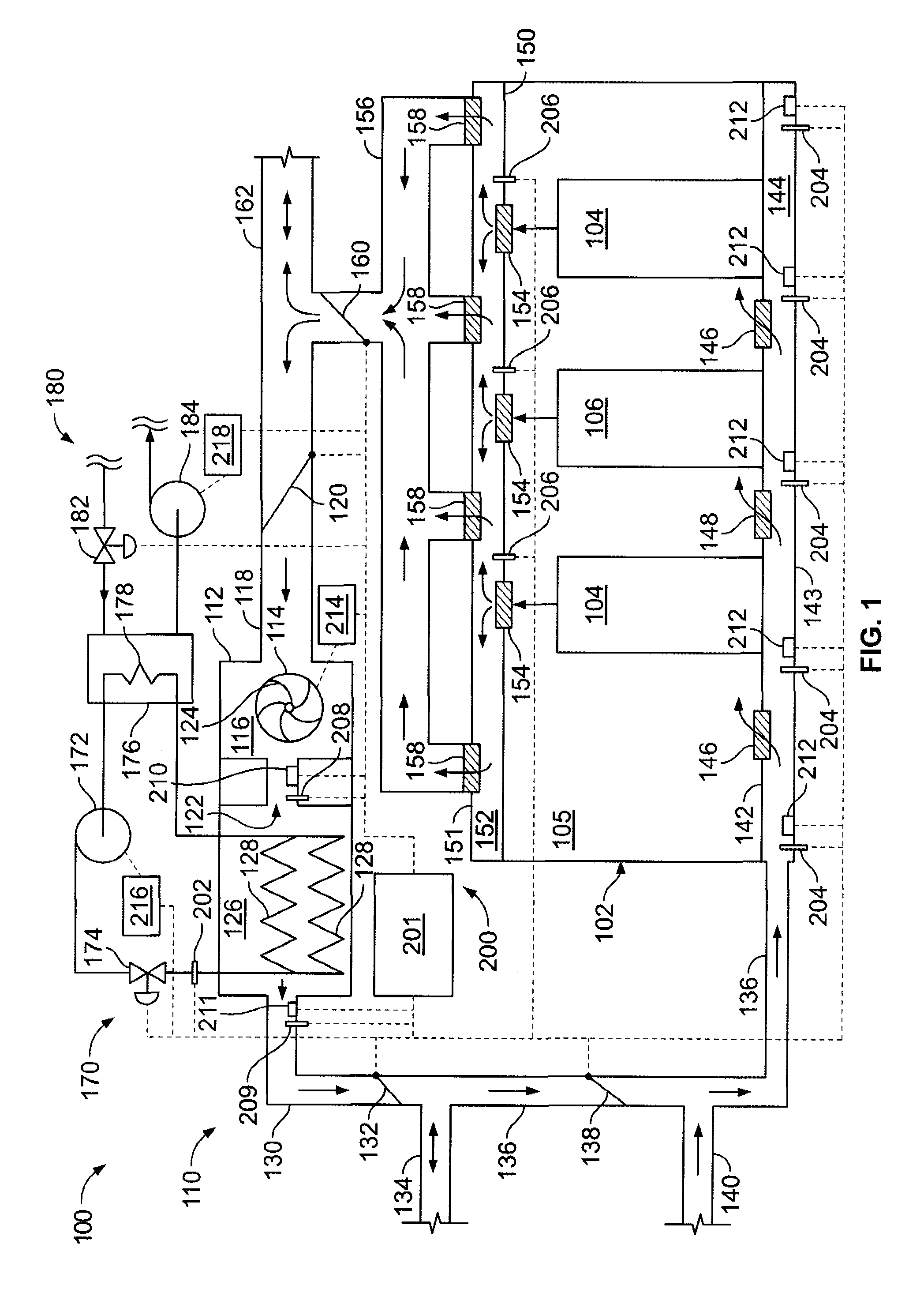
[0009]FIG. 1 is a schematic view of an exemplary data center cooling system 100. System 100 is configured to remove waste heat generation from a data center 102. Data center 102 includes at least one high-density equipment rack system, or high-density rack 104, and at least one low-density equipment rack system, or low-density rack 106. Racks 104 and 106 are substantially similar with the exception of a configuration of electronic components (not shown) within each of racks 104 and 106 and the associated waste heat generation. Typically, waste heat generation from high-density rack 104 is greater than waste heat generation from low-density rack 106 due to the greater concentration of waste heat sources within rack 104 as compared to rack 106. Racks 104 and 106 are positioned within a room 105 of data center 102.

[0010]System 100 includes a fluid transport sub-system that, in the exemplary embodiment, is an air handling sub-system 110. Sub-system 110 is coupled in flow communication w...


PUM


Abstract

A method of cooling at least one electronic component that is configured to generate a predetermined waste heat includes providing a first fluid channeling sub-system that has a first fluid source and at least one controller. The method also includes channeling at least a portion of the first fluid towards the electronic component. The method further includes configuring the at least one controller to facilitate substantially maintaining at least a portion of the first fluid channeling sub-system at a predetermined pressure.

Description

BACKGROUND OF THE INVENTION[0001]The present invention relates generally to cooling systems and more particularly, to methods and apparatus for cooling electronic components.[0002]Some known electronic components generate waste heat energy when energized and this heat energy should be removed to mitigate a potential for component overheating and subsequent malfunction. Computer systems typically include a number of such components, or waste heat sources, that include, but are not limited to, printed circuit boards, mass storage devices, power supplies, and processors. For example, one personal computer system may generate 100 watts to 150 watts of waste heat and some larger computers with multiple processors may generate 250 watts of waste heat. Some known computer systems include a plurality of such larger, multiple-processor computers that are configured into rack-mounted components, and then are subsequently positioned within a racking system. Some known racking systems include 4...

Claims


Application Information

Patent Timeline
IPC IPC(8): F25D23/12H05K7/20
CPCH05K7/20836H05K7/20745F24F2221/40
Inventor MORALES, OSVALDO PATRICIO
Owner AMAZON TECH INC
Why Eureka
Try Eureka