Light guide, light source apparatus, and electronic apparatus

a technology of light guide and light source, applied in the direction of optical radiation measurement, instruments, lighting support devices, etc., can solve the problems of difficult homogeneous light generation and large apparatus, and achieve the effect of effectively exiting and keeping the optical path length as larg

Inactive Publication Date: 2010-05-18
SONY CORP
View PDF9 Cites 29 Cited by
  • Summary
  • Abstract
  • Description
  • Claims
  • Application Information

AI Technical Summary

Benefits of technology

[0011]According to this embodiment of the present invention, since the volume of the light guide section gradually increases, it can effectively guide light that enters from the incident surface and diffuses, condense the light, and cause the condensed light to exit from the exit surface. When the light guide section is bent at a proper angle, light that enters from the incident surface is bent at the desired angle and the light exits from the exit surface. As a result, while the optical path length is kept as large as possible, the light can be diffused and homogeneously radiated. In addition, the light guide and the electronic apparatus equipped therewith can be miniaturized or thinned.
[0014]In an embodiment of the present invention, the light guide section is disposed on a far side of a radiating object and has a side surface which is bent at an angle in a range from 120° to 150°. When the side surface is bent in the range, leakage of light from the side surface can be suppressed. As a result, the amount of light that exits from the exit surface can be increased.
[0018]According to this embodiment, since the second side surface is formed such that it is bent at the first angle, the optical path length can be kept as large as possible. As a result, light that enters from the incident surface can be homogenized. In addition, since the light that enters from the incident surface and is bent at the predetermined angle exits from the exit surface, the light guide and the electronic apparatus can be miniaturized. In addition, light can be caused to be condensed and to exit from the exit surface. As a result, linear light can be caused to effectively exit.
[0019]In an embodiment of the present invention, the first side surface has a first reflection surface connected to the incident surface, and a second reflection surface connected to the first reflection surface at a second angle which is smaller than the first angle and to the exit surface. When the light condensing state of the exit surface, the first angle, and the second angle are properly set, light that travels to the exit surface properly spreads. As a result, the line can be substantially collimated on the exit surface formed in the light condensing shape. Thus, well-shaped light, namely accurately liner shaped light, can be radiated.
[0020]In an embodiment of the present invention, the second side surface has a third reflection surface which is connected to the incident surface and which is gradually apart from the first reflection surface as the third reflection surface is apart from the incident surface. As a result, light that enters from the incident surface can be guided without a loss of the amount of light.

Problems solved by technology

In this case, when light of the light emitting device enters from one end side or both end sides of the light guide, it would be difficult to cause light homogeneously exit from the light guide to the reading object and provide a sufficient amount of light to the reading object.
When many light emitting devices are used to increase the amount of light, the apparatus would become large.

Method used


Image

  • Light guide, light source apparatus, and electronic apparatus
  • Light guide, light source apparatus, and electronic apparatus
  • Light guide, light source apparatus, and electronic apparatus

Examples


Embodiment Construction

[0048]Next, with reference to the accompanying drawings, embodiments of the present invention will be described.

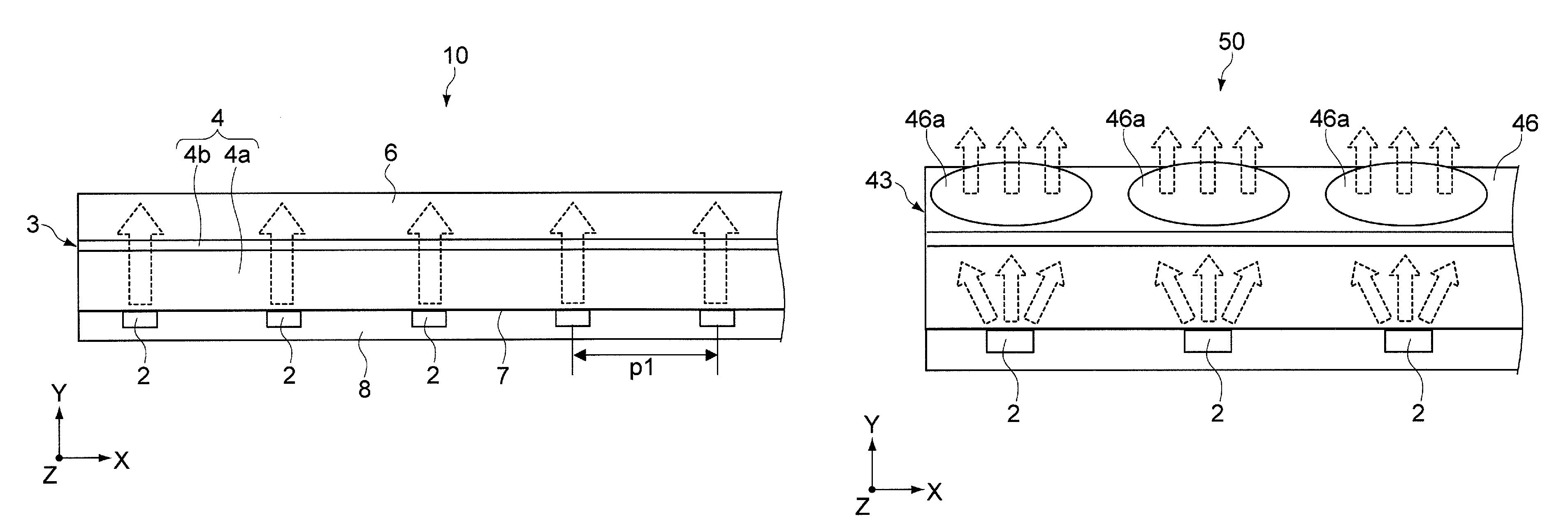
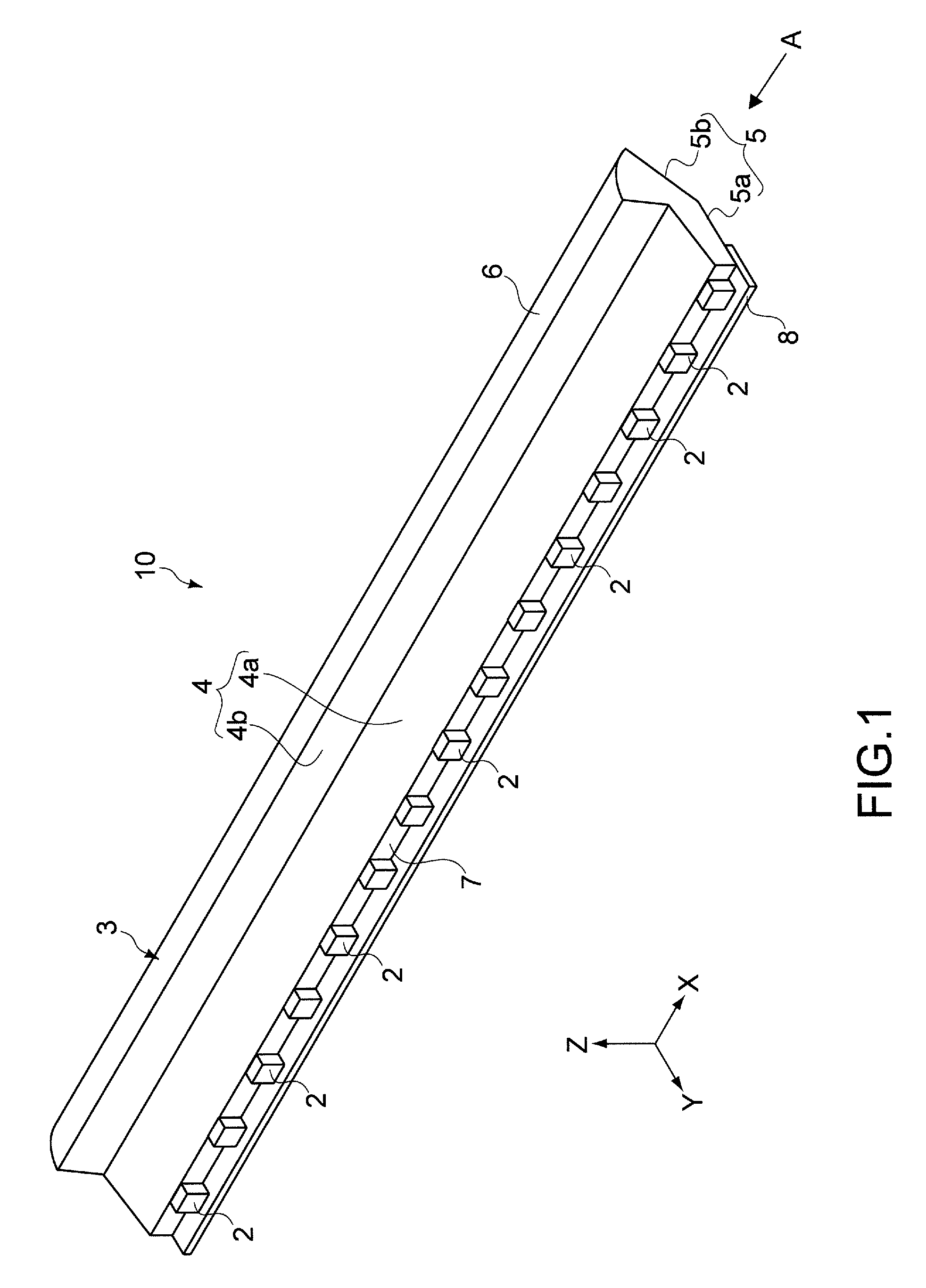
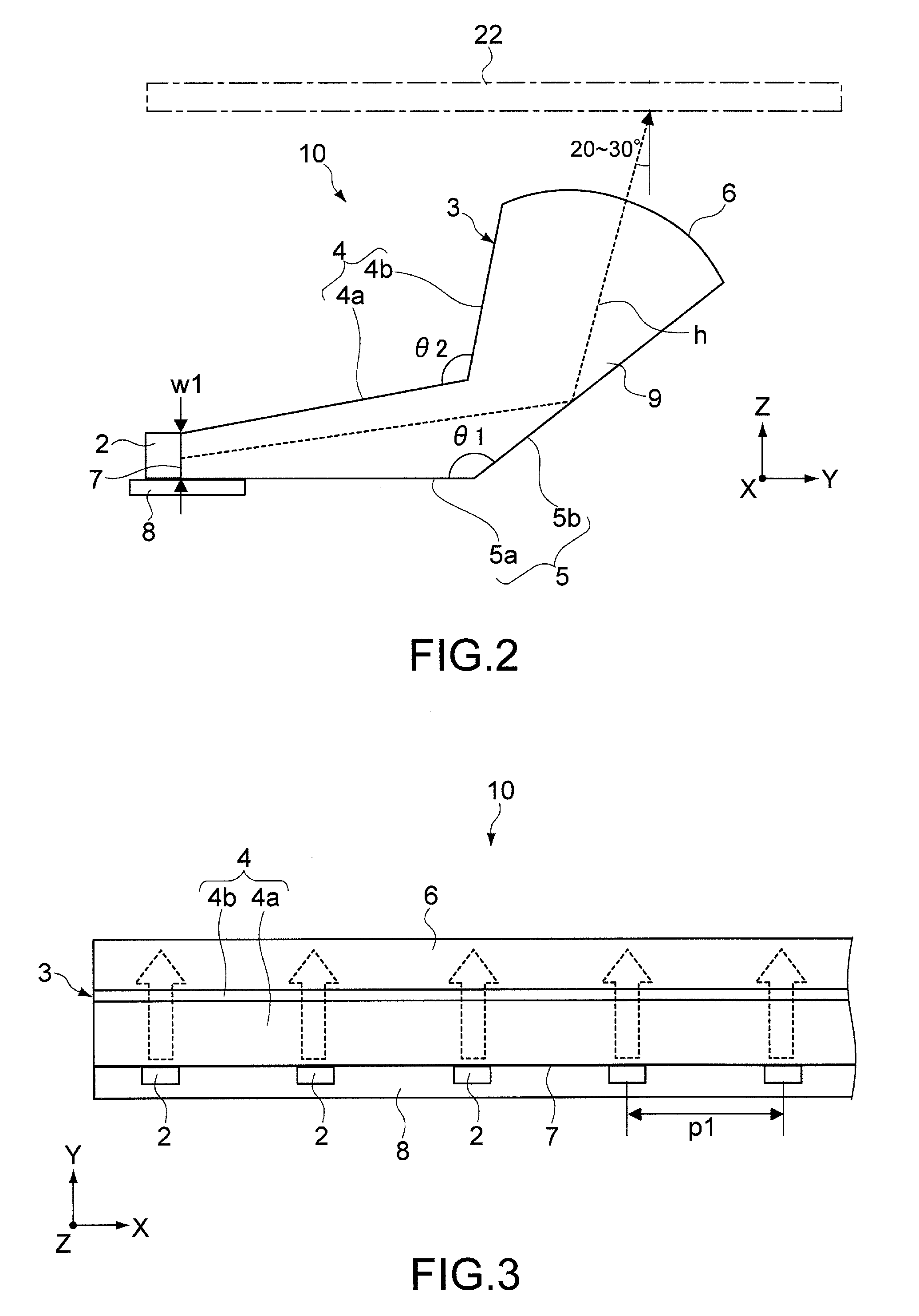
[0049]FIG. 1 is a perspective view showing a light source apparatus 10 according to an embodiment of the present invention. FIG. 2 is a schematic diagram showing the light source apparatus 10 viewed in the direction of arrow A shown in FIG. 1. FIG. 3 is a plan view showing a part of the light source apparatus 10.

[0050]As shown in FIG. 1 and FIG. 3, the light source apparatus 10 includes a plurality of light emitting devices 2 and a light guide 3. The light emitting devices 2 are disposed in line (in the X direction shown in FIG. 1 and FIG. 3). The light guide 3 guides light emitted from the light emitting devices 2 in a predetermined direction. The light emitting devices 2 are disposed, for example, on a printed wiring board 8. Each of the light emitting devices 2 is an LED that has three light emitting sources of red, green, and blue (RGB). The light emitting devices 2 em...


PUM


Abstract

A light guide is disclosed. The light guide includes an incident surface, an exit surface, and a light guide section. Light emitted from a plurality of light emitting devices disposed in line enters from the incident surface. The exit surface is formed in a shape causing light to be concentrated. The light which has entered from the incident surface exits from the exit surface. The light guide section is bent. The volume of the light guide gradually increases in a direction from the incident surface to the exit surface.

Description

CROSS REFERENCES TO RELATED APPLICATIONS[0001]The present invention contains subject matter related to Japanese Patent Application JP 2006-304679 filed in the Japanese Patent Office on Nov. 10, 2006, the entire contents of which being incorporated herein by reference.BACKGROUND OF THE INVENTION[0002]1. Field of the Invention[0003]The present invention relates to a light guide that guides light emitted from a light emitting device and causes the light to linearly exit. The present invention also relates to a light source apparatus and an electronic apparatus that use the light guide.[0004]2. Description of the Related Art[0005]As a light source used for a scanner, a multi-function machine, and so forth that read an image and so forth, a CCFL (Cold Cathode Fluorescent Lighting) lamp has been used. In recent years, to thin or miniaturize the main body of an apparatus, a CIS (Contact Image Sensor) has been used in an image reading section (as disclosed in for example paragraph “0026”, F...

Claims


Application Information

Patent Timeline
Patent Type & Authority Patents(United States)
IPC IPC(8): F21V8/00
CPCG02B6/0018G02B6/0068G02B6/0045G02B6/0036
Inventor KAKIZAKI, AKINORISHIMOMURA, TAKAYOSHIYAMAZAKI, YOSHINORI
Owner SONY CORP
Why Eureka
Try Eureka