Electrostatic precipitator unit

a precipitator and electrostatic technology, applied in electrostatic separation, electrochemical equipment and processes, electrochemical cleaning, etc., can solve the problems of loss of performance, damage to the cell, and contact is susceptible to tracking, and achieve the effect of shorting to ground

Active Publication Date: 2010-05-18
AIR QUALITY ENG
View PDF16 Cites 15 Cited by
  • Summary
  • Abstract
  • Description
  • Claims
  • Application Information

AI Technical Summary

Benefits of technology

[0006]An object of this invention is to provide an electrical contact assembly for supplying current to the ionizer and collector fins of an electrostatic precipitator cell for an electrostatic precipitator unit which is insulated from any ground portions of the unit by an air gap thereby minimizing, if not eliminating, shorting to ground by liquid tracking.
[0007]Another object of this invention is to provide shortened power fins having their lower edges spaced above the lower edges of adjacent ground fins to avoid globules of coolant at the bottom of the ground fins contacting adjacent power fins.
[0008]The electrostatic precipitator unit includes a cabinet containing an electrostatic precipitator cell or cells. The unit is designed to be positioned upon or adjacent a conventional machine tool and communicates with the cutting chamber of the machine tool. When the unit is mounted on the wall, ceiling, etc. adjacent a machine tool, it will be connected to the tool via ducting. A stream of air entrained coolant and particles flows upwardly through the precipitator unit. Ionized coolant and particles collect on the ground plates or fins of the cell. An electrical contact assembly providing high voltage (about up to 4,700 volts DC) current to the collector cell is mounted within the cabinet but isolated from ground by nylon sleeves which provide an electrically insulating air gap which, in effect, eliminates the occurrence of unwanted liquid tracking pathways to ground. One contact of the electrical contact assembly contacts the ionizer bar of the ionizer grid and supplies high voltage (about up to 9,600 volts DC) current thereto. Another contact of the electrical contact assembly contacts the power fins. The power fins have shortened lower edge to prevent tracking across from the adjacent ground fin by agglomerating liquid coolant droplets.

Problems solved by technology

However, these contacts are susceptible to tracking by conductive fluid (coolant) to ground.
This produces shorting and damage to the cell and loss of performance.
This also produces shorting and damage to the cell and loss of performance.

Method used


Image

  • Electrostatic precipitator unit
  • Electrostatic precipitator unit
  • Electrostatic precipitator unit

Examples


Embodiment Construction

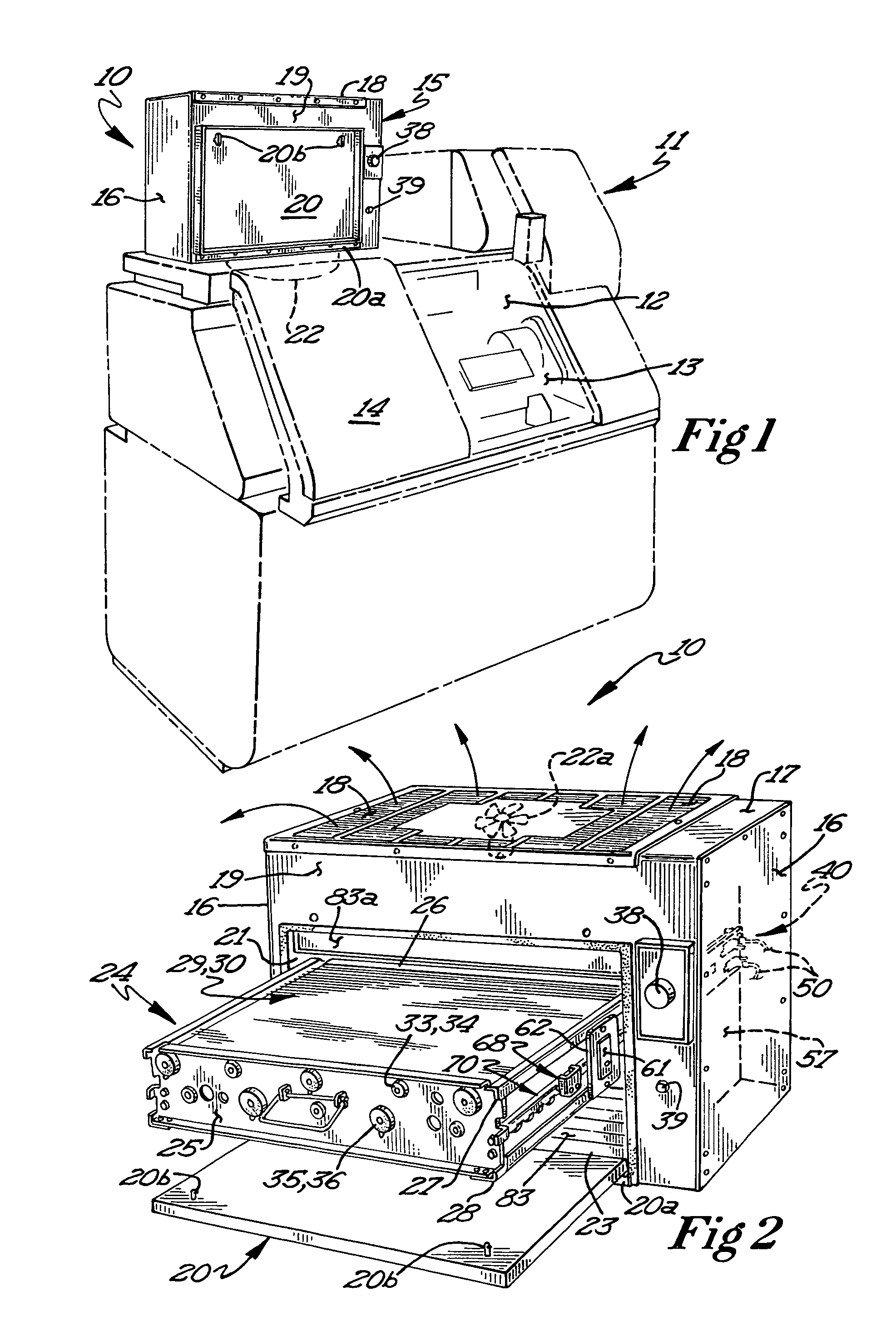
[0018]The novel and improved electrostatic precipitator unit, designated generally by the reference numeral 10, is shown mounted on a machine tool 11. The machine tool 11 may be an automatic screw machine, lathe, metal turning machine or similar type machine tool. The operation of the machine tools are controlled by computer programs in a manner well-known in the industry.

[0019]During operation of the machine tool, liquid coolant is sprayed on the work piece in the work area 13 in the chamber 12. Access to the chamber 12 is by way of an access door 14. The electrostatic precipitator unit 10 serves to remove liquid coolant and particles generated during operation of the machine tool 11.

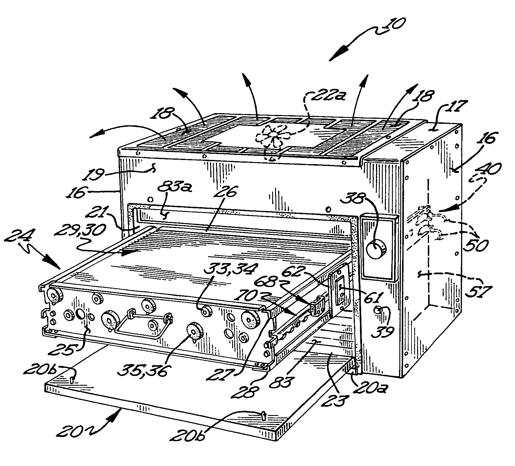
[0020]The electrostatic precipitator unit 10 includes a generally rectangular shaped (parallelopiped) cabinet 15 having opposed side walls 16, a top wall 17, a front wall 19 and a rear wall (not shown). The top wall 17 includes a grill 18 to permit air to flow out of the chamber 23 of the cabinet. The ...


PUM


Abstract

An electrostatic precipitator unit used for the removal of coolant liquid and particles generated by a machine tool includes an electrostatic precipitator cell. The electrostatic precipitator cell includes power and collector ground fins and an ionizer grid positioned below the fins. The lower edges of the power fins are spaced above the collector ground fins to prevent contact of the liquid on the ground fins with the power fins. An electrical contact assembly for supplying electrical current to the ionizer grid and power fins is electrically isolated from all ground contacts by dielectric standoffs which define an insulating air gap. The likelihood of liquid tracking to ground is therefore eliminated.

Description

FIELD OF INVENTION[0001]This invention relates to electrostatic precipitator units which are electrically constructed so as to minimize, if not eliminate, shortening to ground by liquid pathways.BACKGROUND OF THE INVENTION[0002]Electrostatic precipitator devices are used with machine tools for removing and collecting liquid coolant and particles generated during operation of the machine tool. The electrostatic precipitator may be mounted on the machine tool and coolant and particles are entrained in a stream of air drawn through the electrostatic cell plates where the drops of coolant and particles accumulate and drain downwardly. The electrostatic precipitator device may also be mounted on the floor, ceiling, wall, etc. and ducted to the machine tool.[0003]In conventional electrostatic precipitators the electric contacts to the cell plates or fins and cell ionizer are mounted on dielectric elements to insulate the conductive portion of the contact to ground. However, these contacts...

Claims


Application Information

Patent Timeline
Patent Type & Authority Patents(United States)
IPC IPC(8): B03C3/47
CPCB03C3/08B03C3/368B03C3/86B03C3/41B03C2201/10B03C2201/04
Inventor SCHREIBER, MARK MICHAEL
Owner AIR QUALITY ENG
Why Eureka
Try Eureka