Differential amplifier with current source controlled through differential feedback

a technology of differential feedback and amplifier, which is applied in the direction of differential amplifiers, dc-amplifiers with dc-coupled stages, amplifiers with semiconductor devices/discharge tubes, etc., can solve the problems of deteriorating other dynamic performance characteristics of amplifiers, complicated operation of differential amplifiers, and complex circuits, so as to increase the gain value of the single stage of amplification

Active Publication Date: 2010-05-18
HARRIS GLOBAL COMM INC
View PDF9 Cites 12 Cited by
  • Summary
  • Abstract
  • Description
  • Claims
  • Application Information

AI Technical Summary

Benefits of technology

[0007]The differential amplifier further includes third and fourth electrical paths coupled, respectively, to first and second biasing nodes of the first and second transistors for providing a differential voltage input signal between the first and second biasing nodes. In addition, the inverting and non-inverting input nodes, respectively, of the feedback amplifier are connected directly to the first and second collectors, and the output end of the feedback amplifier is connected directly to an input node of the tail-current transistor. The first and second electrical paths provide the differential voltage output as a single stage of amplification with respect to the third and fourth electrical paths. The feedback amplifier is configured to increase the current provided through each of the first and second electrical paths and, in turn, substantially increase a gain value of the single stage of amplification.

Problems solved by technology

In order to increase the gain of the differential amplifier, differential cascaded amplifiers are necessary, thus making the circuit more complex.
This further complicates the operation of the differential amplifier and deteriorates other dynamic performance characteristics of the amplifier, such as its response time.

Method used


Image

  • Differential amplifier with current source controlled through differential feedback
  • Differential amplifier with current source controlled through differential feedback
  • Differential amplifier with current source controlled through differential feedback

Examples


Embodiment Construction

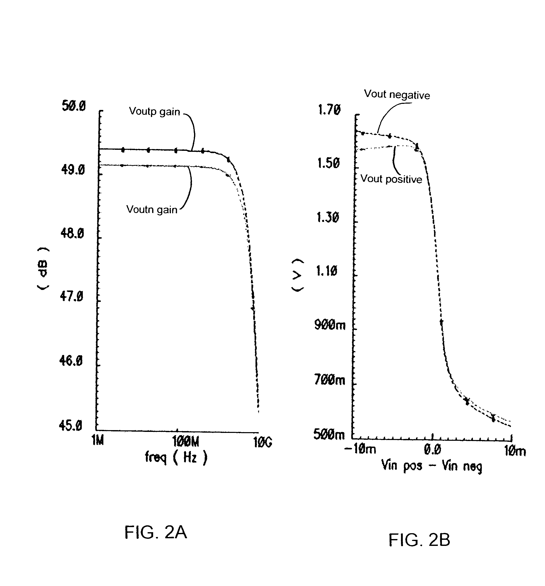
[0031]As will be explained, an embodiment of the present invention provides a differential amplifier having a high gain of approximately 50 to 60 dB. This high gain is advantageously achieved with a single amplification stage, without any need for complicated transistor arrangements, such as cascaded amplifier arrangements or frequency compensation arrangements.

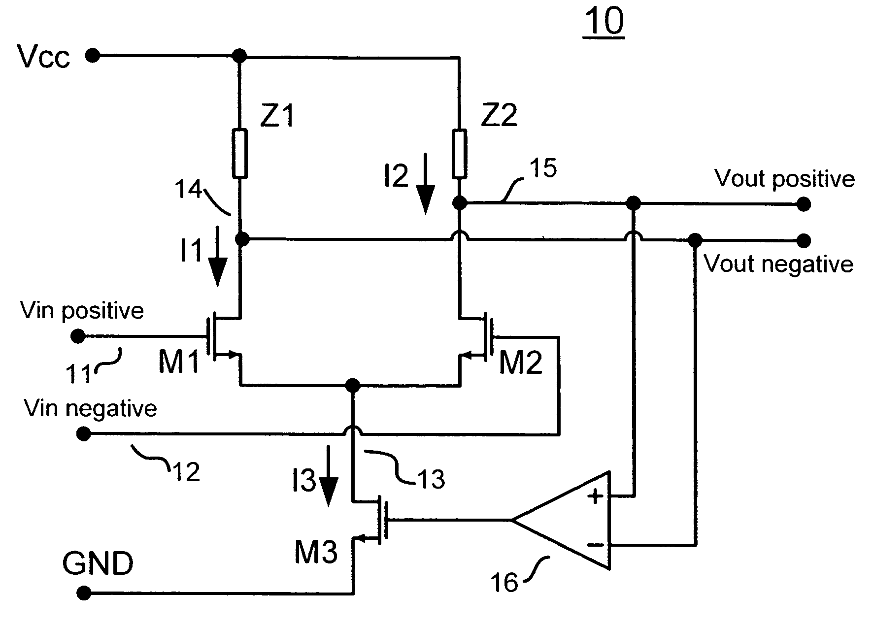
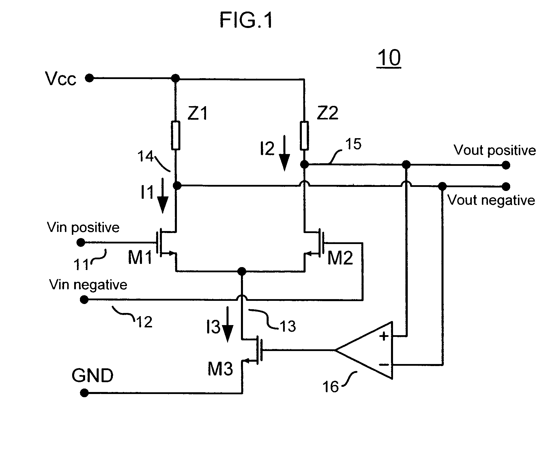
[0032]Referring to FIG. 1, there is shown a single stage differential amplifier, generally designated as 10. Differential amplifier 10 includes a pair of transistors M1 and M2, tail-current transistor M3 and impedance load elements Z1 and Z2. One end of each of the impedance loads is connected to a positive voltage potential of Vcc, and one end of tail-current transistor M3 is connected to another voltage potential, such as a ground potential.

[0033]As shown, transistor M1 and impedance load element Z1 form a first electrical path, while transistor M2 and impedance load element Z2 form a second electrical path. The first elect...


PUM


Abstract

A differential amplifier includes a first electrical path formed between a first transistor and a first load impedance; a second electrical path formed between a second transistor and a second load impedance; a tail-current transistor coupled to the first and second transistors; an input end of a feedback amplifier coupled directly to the first and second electrical paths for receiving a differential voltage output signal; and an output end of the feedback amplifier coupled directly to the tail-current transistor for adjusting the current provided through each of the first and second electrical paths. The feedback amplifier includes a non-inverting input node and an inverting input node, each node coupled directly to one or the other of the first and second electrical paths.

Description

FIELD OF THE INVENTION[0001]The present invention relates, in general, to a differential amplifier. More specifically, the present invention relates to a high gain, single stage differential amplifier with a current source that is controlled through differential feedback.BACKGROUND OF THE INVENTION[0002]Differential amplifiers are electronic devices for amplifying a voltage difference between two input signals. A differential amplifier typically includes two electrical paths that are independently coupled to a voltage source at one end, and that are together coupled to a voltage or current source at an opposite end. Each electrical path usually includes a transistor element and a resistance element. Two differential input signals may be applied to the transistor elements, and a differential output signal may be extracted from each electrical path between its transistor element and resistance element. The two electrical paths are usually designed to substantially match each other, su...

Claims


Application Information

Patent Timeline
Patent Type & Authority Patents(United States)
IPC IPC(8): H03F3/45
CPCH03F3/45085
Inventor PERA, FLORIN
Owner HARRIS GLOBAL COMM INC
Why Eureka
Try Eureka