
Differential quadrature phase-shift modulator and method for setting driving voltage thereof

a technology of phase-shift modulator and different quadrature, applied in the direction of digital transmission, optics, instruments, etc., can solve the problems of imbalance between pb>, deterioration of signal quality, and poor extinction ratio of modulator b>130/b>, so as to suppress the deterioration of the extinction ratio of dqpsk modulator, improve yield and cost-reduction of optical transmitters, and enhance the quality of dqp

Inactive Publication Date: 2010-05-18
FUJITSU LTD
View PDF27 Cites 22 Cited by
  • Summary
  • Abstract
  • Description
  • Claims
  • Application Information

AI Technical Summary

Benefits of technology

The present invention provides a differential quadrature phase shift modulator that can produce superior signal quality even when there are variations in manufacture due to individual differences. The invention also provides a method for setting the driving voltage signals for the modulator based on signal quality. The invention aims to address the problem of variations in signal quality caused by variations in manufacture of the device.

Problems solved by technology

In this case, despite a phase difference between the symbols of four values assuming a value of π / 2 in an ideal state, the phase difference deviates from π / 2, to thus give rise to a deviation α. Therefore, there is a problem of the deviation entailing deterioration of signal quality.
Such an imbalance arises between P1 and P2 in a case where the extinction ratio of the modulator 130 is not good.
However, the technique does not disclose any configuration for making signal quality of the DQPSK modulator excellent in response to an individual difference between extinction ratios due to variations in manufacture of devices.

Method used


Image

  • Differential quadrature phase-shift modulator and method for setting driving voltage thereof
  • Differential quadrature phase-shift modulator and method for setting driving voltage thereof
  • Differential quadrature phase-shift modulator and method for setting driving voltage thereof

Examples


first embodiment

[A1] Description of a First Embodiment

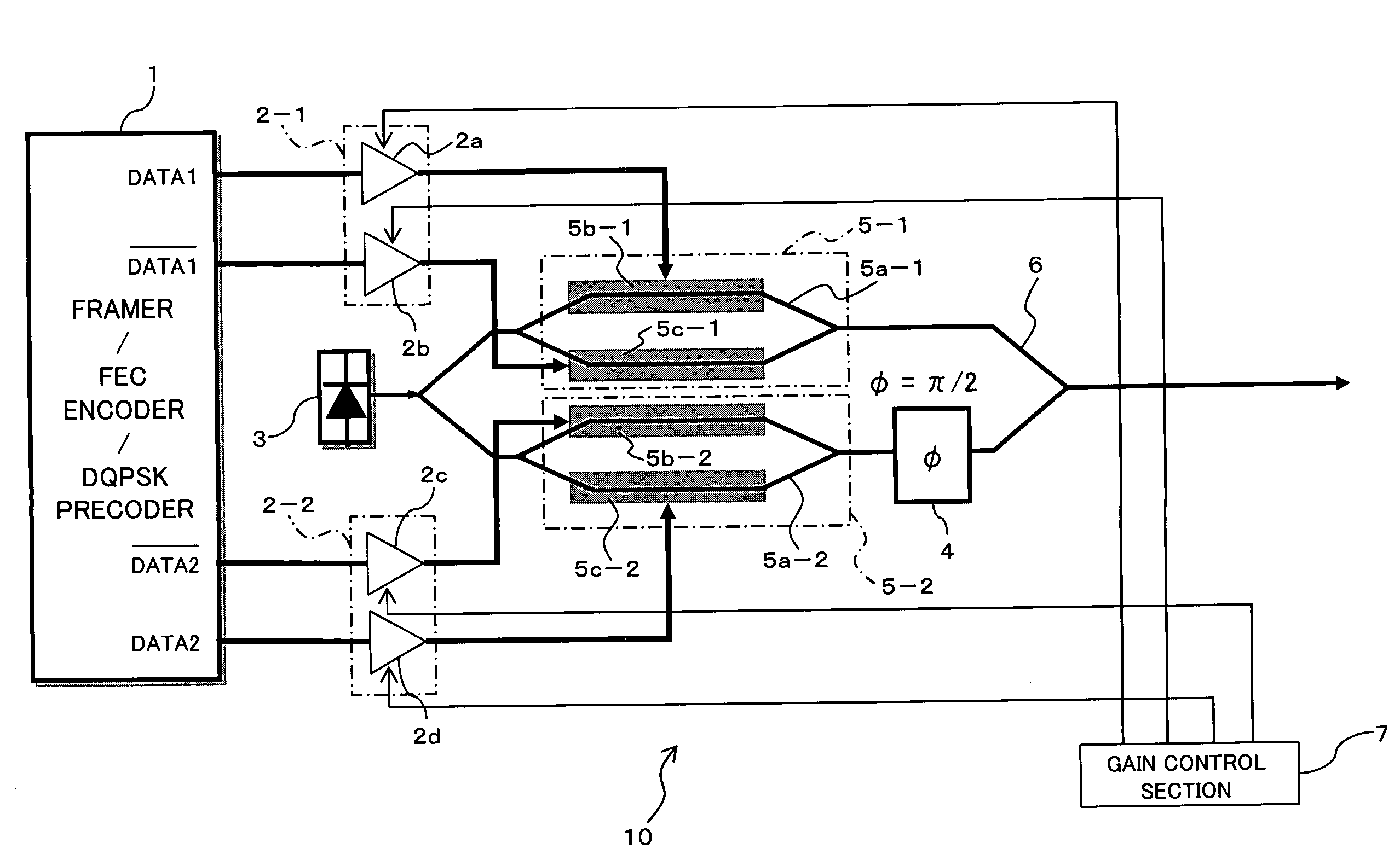
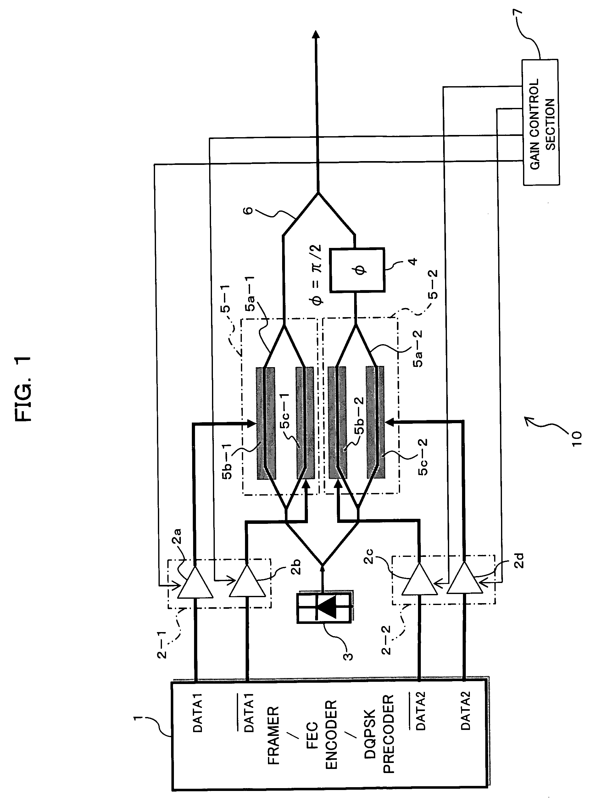
[0079]FIG. 1 is a view showing a differential quadrature phase-shift-keying modulator (DQPSK modulator) 10 applied to a first embodiment of the present invention. The DQPSK modulator 10 shown in FIG. 1 has a transmission data processing section 1, amplifying sections 2-1 and 2-2, a CW (Continuous Wave) light source 3, a π / 2 phase modulator 4, two Mach-Zehnder phase modulators 5-1 and 5-2, an MZM interferometer 6, and a gain control section 7 for controlling gains of the amplifying sections 2-1, 2-2, all of these elements being basically similar to those (reference numerals 131 to 136) shown in FIG. 23 described previously.

[0080]Like that (see reference numeral 131) shown in FIG. 23, the transmission data processing section 1 has the function of a DQPSK precoder for effecting encoding in which is reflected information about a difference between the code of current data and the code of data preceding the current data by one bit, as well as having ...

second embodiment

[B] Description of a Second Embodiment

[0160]FIG. 19 is a view showing a differential quadrature phase-shift-keying modulator (DQPSK modulator) 30 applied to a second embodiment of the present invention. The DQPSK modulator 30 shown in FIG. 19 has the transmission data processing section 1, the first, second amplifying sections 2-1 and 2-2, the phase modulators (Mach-Zehnder-type modulators) 5-1 and 5-2, the π / 2 phase shift section 4, and the MZM interferometer 6, all of which are analogous to those of the previously-described first embodiment. Further, the DQPSK modulator 30 also has a wavelength-variable light source 31 serving as a CW light source; a wavelength control section 32 for controlling the wavelength of an output from the wavelength-variable light source 31; a gain control section 33; and a storage section 34. In FIG. 19, those reference numerals which are identical with those shown in FIG. 1 designate substantially the same sections.

[0161]The first, second amplifying se...


PUM

PropertyMeasurementUnit
driving voltageaaaaaaaaaa
phaseaaaaaaaaaa
phase differenceaaaaaaaaaa

Abstract

The present invention is directed toward a method for setting a driving voltage of a differential quadrature phase-shift modulator, this method making signal quality superior in response to an individual difference in extinction ratio due to variations in manufacture of a device. To this end, signal quality of differential quadrature phase-shift modulated light output from a differential quadrature phase-shift modulator is acquired. An average amplitude of a first or second driving voltage signal is adjusted according to the signal quality of the thus-acquired differential quadrature phase-shift modulated light.

Description

BACKGROUND OF THE INVENTION[0001]1) Field of the Invention[0002]The present invention relates to differential quadrature phase-shift modulator suitable for use in a transmitter of an optical transmission system, as well as to a method for setting a driving voltage of the differential quadrature phase-shift modulator.[0003]2) Background of the Invention[0004]In recent years, increasing demand has arisen for introduction of a 40-Gbit / s optical transmission system of the next generation. In addition, a transmission distance and frequency utilization efficiency equivalent to those achieved by a 10 Gbit / s system have been sought. In an effort to meet such demands, brisk research and development has been carried out on a DPSK (Differential Phase Shift Keying) modulation scheme, which is superior to an NRZ (Non-Return to Zero) modulation scheme having hitherto been applied to a system of 10 Gb / s or less in terms of optical-signal-to-noise ratio (OSNR) resistance and nonlinear resistance. I...

Claims


Application Information

Patent Timeline
Patent Type & Authority Patents(United States)
IPC IPC(8): H04B10/04H04B10/00G02F1/01H04B10/07H04B10/516H04B10/556H04B10/564H04B10/572H04B10/588H04B10/61
CPCG02F1/2255H04B10/505H04L27/2096H04B10/50572H04B10/5561H04L27/2075H04B10/5053G02F2001/212G02F1/212
Inventor NAKASHIMA, HISAOHOSHIDA, TAKESHI
Owner FUJITSU LTD
Learn More