Particulate filter having expansible capture structure for particulate removal

a technology of particulate filter and capture structure, which is applied in the field of particle filter, to achieve the effect of facilitating mechanical removal of trapped particulate matter, reducing porosity and reducing porosity

Inactive Publication Date: 2010-05-25
INT TRUCK INTPROP LLC
View PDF8 Cites 3 Cited by
  • Summary
  • Abstract
  • Description
  • Claims
  • Application Information

AI Technical Summary

Benefits of technology

[0010]One general aspect of the invention relates to a combustion engine that when running generates exhaust containing particulate matter and that comprises an exhaust system containing a particulate filter that traps particulate matter in exhaust passing through the exhaust system. The particulate filter comprising a particulate trapping medium that when the engine is running has a relatively lesser porosity for trapping particulate matter in exhaust, and that is operable to have a relatively greater porosity for facilitating mechanical removal of trapped particulate matter.

Problems solved by technology

Moreover, the burning of trapped DPM may contribute to the build-up of ash, a non-combustible particulate.

Method used


Image

  • Particulate filter having expansible capture structure for particulate removal
  • Particulate filter having expansible capture structure for particulate removal
  • Particulate filter having expansible capture structure for particulate removal

Examples


Embodiment Construction

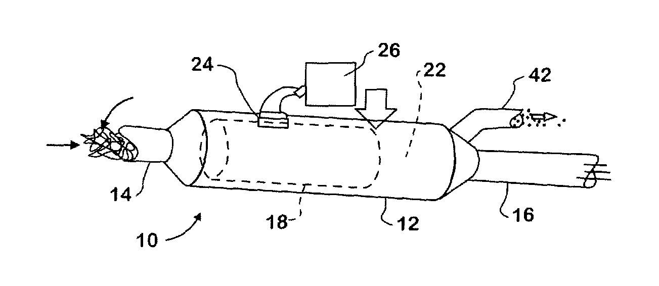
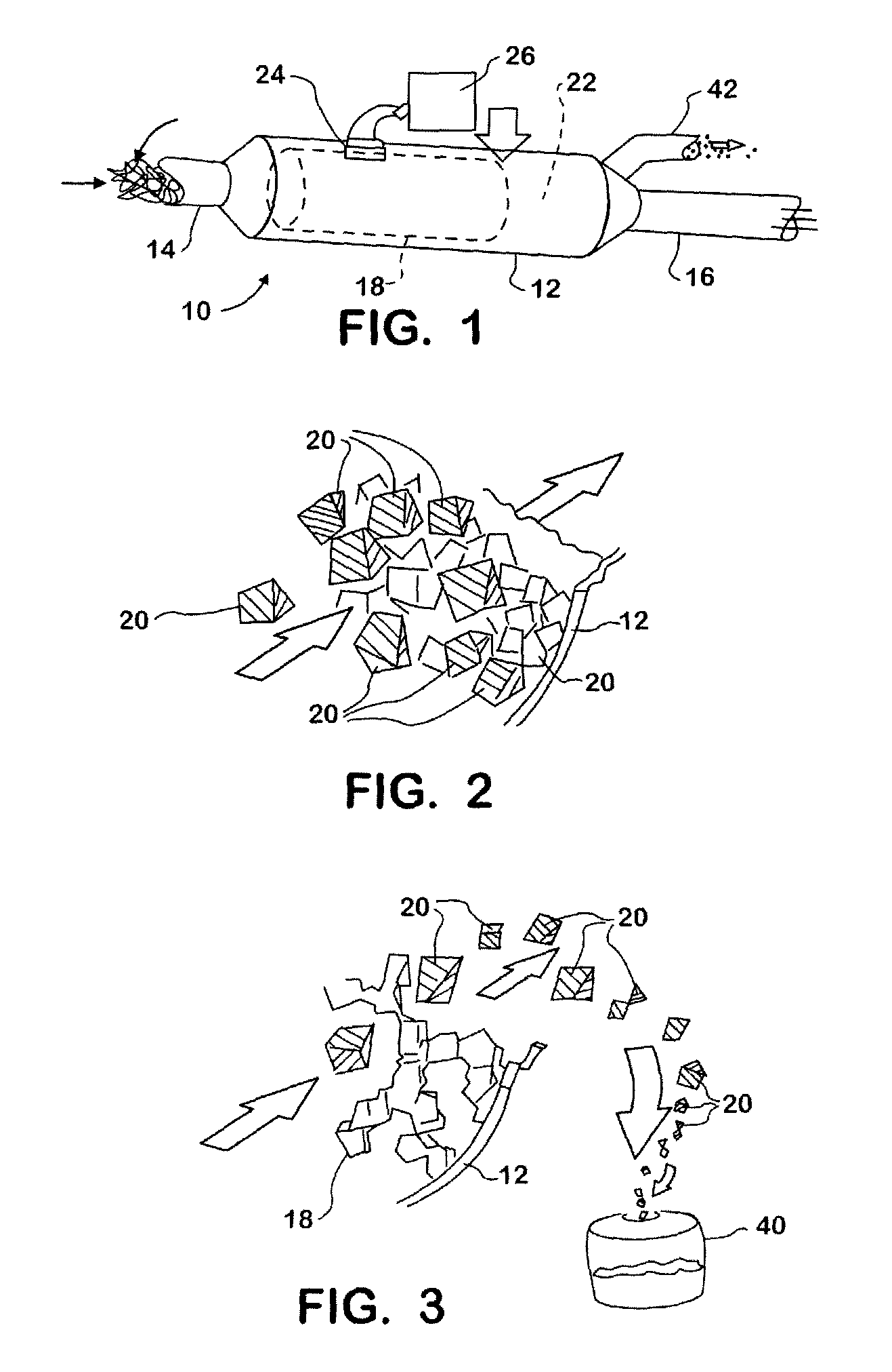
[0020]FIG. 1 shows a particulate filter 10 suitable for placement in an engine exhaust system for trapping diesel particulate matter in exhaust passing through the filter. Filter 10 comprises a casing 12 having an exhaust inlet 14 through which exhaust enters and an exhaust outlet 16 through which exhaust exits. A particulate trapping medium 18 is disposed within the interior of casing 12 between inlet 14 and outlet 16. As exhaust passes through medium 18, the medium traps diesel particulate matter (DPM) when in a relatively less porous condition shown in FIG. 2 where the DPM is marked by the reference numeral 20. The relatively lesser porosity condition allows exhaust gas, and some DPM having sizes smaller than the porosity of the medium, to pass through to outlet 16 and then into the surrounding atmosphere.

[0021]Medium 18 is constructed to be expansible and contractible so as to vary its porosity. A condition of relatively greater porosity is shown in FIG. 3. The material forming ...


PUM

PropertyMeasurementUnit
porosityaaaaaaaaaa
magnetic fieldaaaaaaaaaa
electric fieldaaaaaaaaaa

Abstract

A combustion engine comprising an exhaust system containing a particulate filter (10, 52) for trapping particulate matter in engine exhaust passing through the exhaust system. A particulate trapping medium (18) inside a casing is selectively operable to a relatively lesser porosity for trapping particulate matter in the exhaust and to a relatively greater porosity for facilitating removal of trapped particulate matter during cleaning.

Description

FIELD OF THE INVENTION[0001]This invention relates generally to particulate filters, especially those that are used to trap particulate matter in engine exhaust, and to systems and methods for removing trapped particulates.BACKGROUND OF THE INVENTION[0002]A known system for treating exhaust gas passing through an exhaust system of a diesel engine comprises a diesel oxidation catalyst (DOC) associated with a diesel particulate filter (DPF). The combination of these two exhaust gas treatment devices promotes chemical reactions in exhaust gas and traps diesel particulate matter (DPM) as exhaust flows through the exhaust system from the engine, thereby preventing significant amounts of pollutants such as hydrocarbons, carbon monoxide, soot, SOF, and ash, from entering the atmosphere.[0003]While an engine is running, the existence of certain conditions enables regeneration of a DPF to be initiated. Various techniques are available for developing temperatures sufficiently high to initiate...

Claims


Application Information

Patent Timeline
Patent Type & Authority Patents(United States)
IPC IPC(8): F01N3/00
CPCF01N3/0224F01N3/023F01N2330/60F01N2330/08F01N3/027Y10S55/30
Inventor BRADLEY, JAMES C.KLINGER, RODNEY J.PENALOZA, JOSEPH T.
Owner INT TRUCK INTPROP LLC
Why Eureka
Try Eureka