Remote laser welding of overlapping metal workpieces at fast speeds

a laser welding and metal workpiece technology, applied in welding/soldering/cutting articles, manufacturing tools, transportation and packaging, etc., can solve the problems of degrading the mechanical properties of the weld joint, affecting the welding effect, so as to enhance the strength of the resultant laser weld joint, improve the effect of disturban

Active Publication Date: 2021-03-23
GM GLOBAL TECH OPERATIONS LLC
View PDF26 Cites 3 Cited by
  • Summary
  • Abstract
  • Description
  • Claims
  • Application Information

AI Technical Summary

Benefits of technology

[0013]A scanning optic laser head of a remote laser welding apparatus directs the laser beam at the top surface of the workpiece stack-up and advances the laser beam along the beam travel pattern. The scanning optic laser head includes optical components that can move the laser beam relative to the plane at the top surface of the workpiece stack-up and also adjust a focal point of the laser beam up or down along a longitudinal axis of the laser beam. In this way, the optical components can be rapidly indexed to advance the laser beam and consequently translate the keyhole and the molten weld pool anywhere within an effective operating envelope and along a wide variety of beam travel patterns. Any type of beam pattern may be traced by the laser beam including a linear stitch pattern, a curved or “C-shaped” staple pattern, a circle spot pattern, a spiral pattern, an oscillating pattern, or any other type of pattern. When tracing the designated beam pattern—whatever it is—the laser beam is advanced from a start point (where impingement is initiated) to an end point (where impingement is terminated) at a travel speed that is relatively high compared to conventional practices. Specifically, the travel speed of the laser beam along the beam travel path ranges from 8 m / min to 100 m / min or, more narrowly, from 12 m / min to 50 m / min, while maintaining the presence of the keyhole.
[0014]The high travel speed of the laser beam and the corresponding translation of the keyhole and the molten weld pool are thought to enhance the strength of the resultant laser weld joint. Without being bound by theory, the high travel speed of the laser beam is believed to generate a strong stirring effect within the molten weld pool during translation of the weld pool relative to the top surface of the workpiece stack-up along the beam travel pattern. The more vigorous stirring induced in the molten weld pool better agitates the weld pool to drive the expulsion of entrained gas vapors (e.g., zinc, hydrogen, etc.) through the keyhole and away from the weld site of the workpiece stack-up. It also better disturbs the surface coating(s) in and around the beam travel pattern so as to minimize the likelihood that weld defects derived from the surface coating(s) will accumulate within the resolidified composite workpiece material of the weld joint and negatively affect the strength of the joint and other related properties. The high laser beam travel speed is thus believed to result in less porosity and other weld defects within the weld joint, compared to slower conventional travel speeds, while also minimizing the potential for burn-through and blowholes.

Problems solved by technology

The use of laser welding to join together workpieces that include surface coatings can present challenges.
When an adequate escape outlet is not provided, zinc vapors may remain trapped in the molten weld pool as it cools and solidifies, which may lead to defects in the resulting weld joint—such as porosity—that can degrade the mechanical properties of the weld joint to such an extent that the joint may be deemed non-conforming.
Unlike zinc-based materials, aluminum-based material coatings do not boil at a temperature below the melting point of steel, so they are unlikely to produce high-pressure vapors at the faying interface(s) of the workpiece stack-up.
The introduction of such disparate molten materials into the molten weld pool can lead to a variety of weld defects that have the potential to degrade the mechanical properties of the laser weld joint.
Molten aluminum or aluminum alloys (e.g., AlSi, AlZn, or AlMg alloys), for instance, can dilute the steel content of the molten weld pool and form brittle Fe—Al intermetallic phases within the weld joint as well as negatively affect the cooling behavior of the molten weld pool.
But the presence of the surface coating also makes it more challenging to autogeneously fusion weld aluminum workpieces together by way of laser welding.
One of the main challenges involved in laser welding aluminum workpieces is the high solubility of hydrogen in the molten weld pool.
Upon solidification of the molten weld pool, dissolved hydrogen becomes trapped, leading to porosity, or it outgases to cause blowholes.
In addition to the challenges posed by hydrogen solubility in the molten weld pool, the surface coating of an aluminum workpiece is also believed to contribute to the formation of weld defects in the final laser weld joint.
When, for example, the surface coating is a passive refractory oxide coating, the coating is difficult to break apart and disperse due to its high melting point and mechanical toughness.
As a result, residual oxides and micro-cracks are oftentimes found in the laser weld joint.
The other materials mentioned above that may constitute the surface coating can present similar issues and may ultimately affect and degrade the mechanical properties of the weld joint.

Method used


Image

  • Remote laser welding of overlapping metal workpieces at fast speeds
  • Remote laser welding of overlapping metal workpieces at fast speeds
  • Remote laser welding of overlapping metal workpieces at fast speeds

Examples


Embodiment Construction

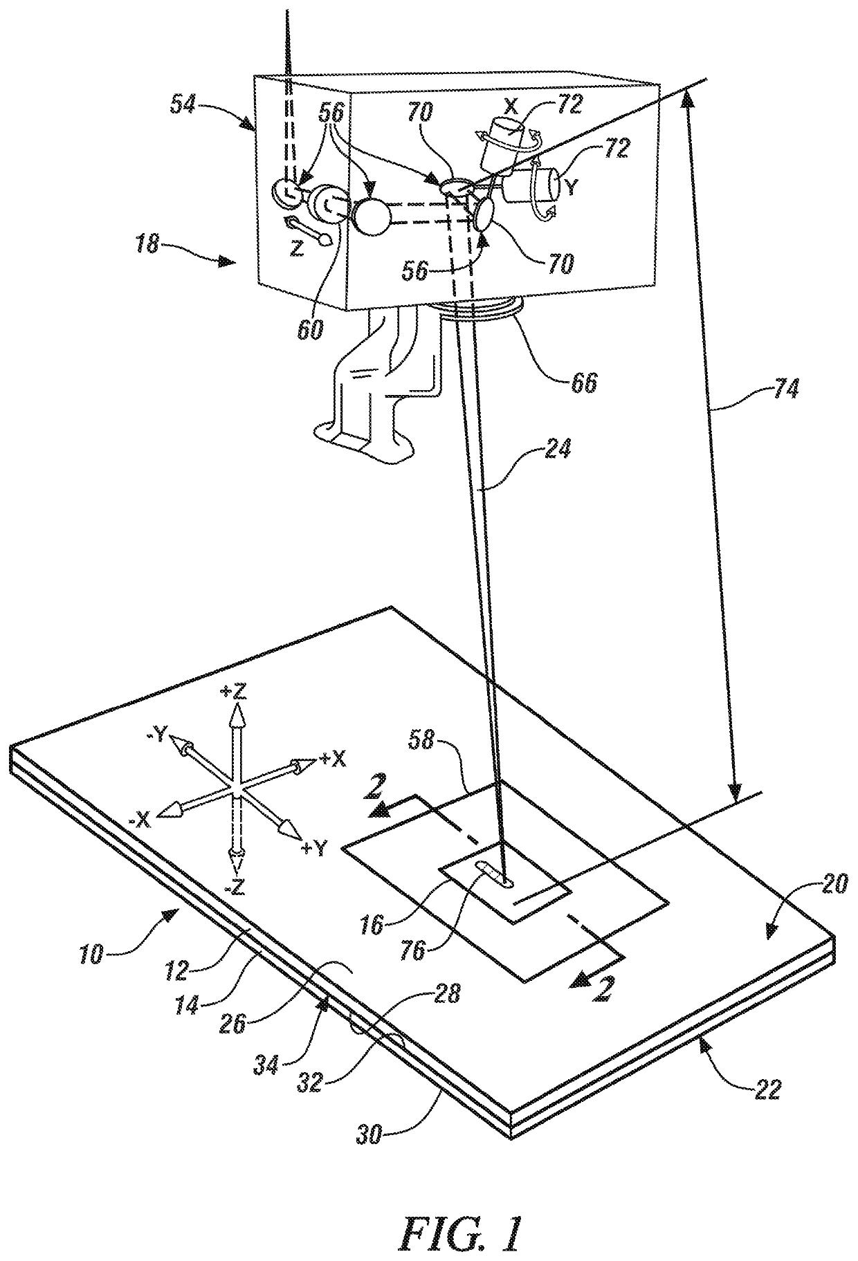
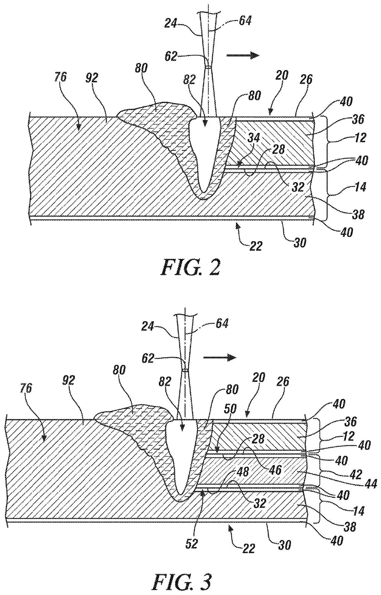
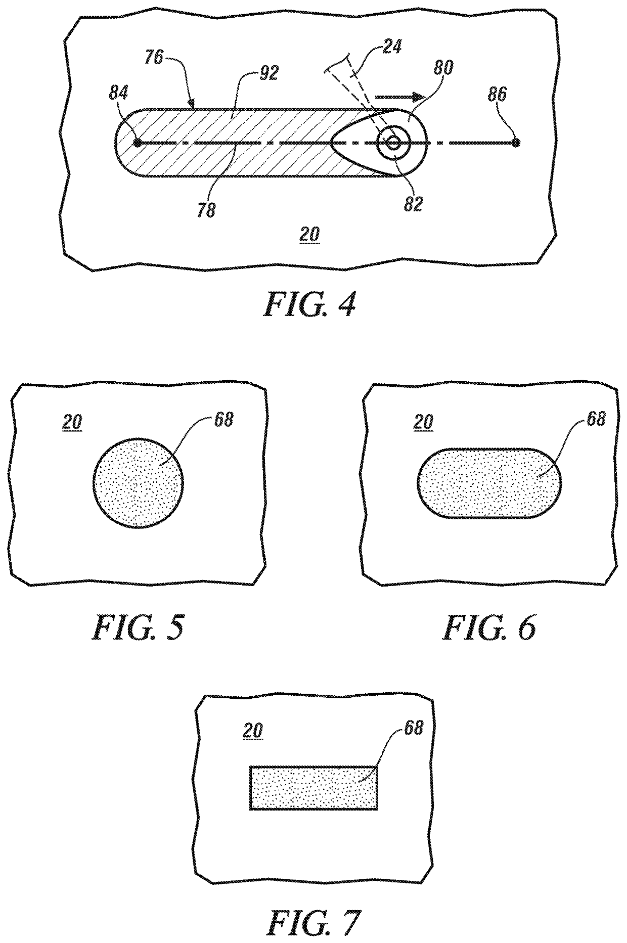
[0027]The disclosed method of laser welding a workpiece stack-up comprised of two or more overlapping metal workpieces calls for advancing a laser beam relative to a plane of a top surface of the workpiece stack-up along a beam travel pattern at a high beam travel speed of greater than 8 m / min, and more preferably greater than 12 m / min, while maintaining a penetrating keyhole. The laser beam may be a solid-state laser beam or a gas laser beam depending on a variety of factors including, among others, the characteristics of the metal workpieces being joined. Some notable solid-state lasers that may be used are a fiber laser, a disk laser, a direct diode laser, and a Nd:YAG laser, and a notable gas laser that may be used is a CO2 laser, although other types of lasers may certainly be used so long as they are able to create the keyhole and surrounding molten weld pool. Due to the high laser beam travel speeds employed and the possible geometric complexity of the beam travel pattern tra...


PUM

PropertyMeasurementUnit
poweraaaaaaaaaa
focal lengthaaaaaaaaaa

Abstract

A method of laser welding a workpiece stack-up (10) that includes at least two overlapping metal workpieces (12, 14) comprises advancing a laser beam (24) relative to a plane of a top surface (20) of the workpiece stack-up (10) from a start point (84) to an end point (86) along a beam travel pattern (78) at a high laser beam travel speed of greater than 8 meters per minute. The two or more overlapping metal workpieces (12, 14) may be steel workpieces or they may be aluminum workpieces, and at least one of the metal workpieces (12, 14) includes a surface coating (40). Advancing the laser beam (24) along the beam travel pattern (78) forms a weld joint (76), which includes resolidified composite workpiece material derived from each of the metal workpieces (12, 14) penetrated by a molten weld pool (80), that fusion welds the metal workpieces (12, 14) together. The relatively high laser beam travel speed contributes to improve strength properties of the weld joint (76).

Description

TECHNICAL FIELD[0001]The technical field of this disclosure relates generally to laser welding and, more particularly, to a method of remote laser welding together two or more overlapping metal workpieces in which at least one of the workpieces includes a surface coating.BACKGROUND[0002]Laser welding is a metal joining process in which a laser beam is directed at a metal workpiece stack-up to provide a concentrated energy source capable of effectuating a weld joint between the overlapping constituent metal workpieces. In general, two or more metal workpieces are first aligned and stacked relative to one another such that their faying surfaces overlap and confront to establish a faying interface (or faying interfaces) within an intended weld site. A laser beam is then directed at a top surface of the workpiece stack-up. The heat generated from the absorption of energy from the laser beam initiates melting of the metal workpieces and establishes a molten weld pool within the workpiece...

Claims


Application Information

Patent Timeline
Patent Type & Authority Patents(United States)
IPC IPC(8): B23K26/24B23K26/244B23K26/073B23K26/22B23K26/322B23K26/082B23K26/00B23K101/00B23K101/18B23K101/34B23K103/04B23K103/10B23K103/18
CPCB23K26/244B23K26/0006B23K26/073B23K26/0732B23K26/0736B23K26/082B23K26/22B23K26/322B23K2101/006B23K2101/18B23K2101/34B23K2103/04B23K2103/10B23K2103/18
Inventor YANG, DAVIDTAO, WU
Owner GM GLOBAL TECH OPERATIONS LLC
Why Eureka
Try Eureka