Tractor with automatic steering arrangement

a technology of automatic steering and tractor, which is applied in the direction of steering components, position/direction control, application, etc., can solve the problems of limit the transport speed of these windrowers and the inability of tractor to move uncontrollabl

Active Publication Date: 2010-05-25
MACDON INDS
View PDF18 Cites 46 Cited by
  • Summary
  • Abstract
  • Description
  • Claims
  • Application Information

AI Technical Summary

Problems solved by technology

There has been a limit to the transport speed of these windrowers due to instability at high speed with the drive wheels ahead of the castor wheels (cab forward).
This arrangement has been found to have a serious problem in that the arrangement loses control in a situation where there is no flow to the motors for example in a slight downhill situation so that the tractor can move uncontrolled to any location.

Method used


Image

  • Tractor with automatic steering arrangement
  • Tractor with automatic steering arrangement
  • Tractor with automatic steering arrangement

Examples


Embodiment Construction

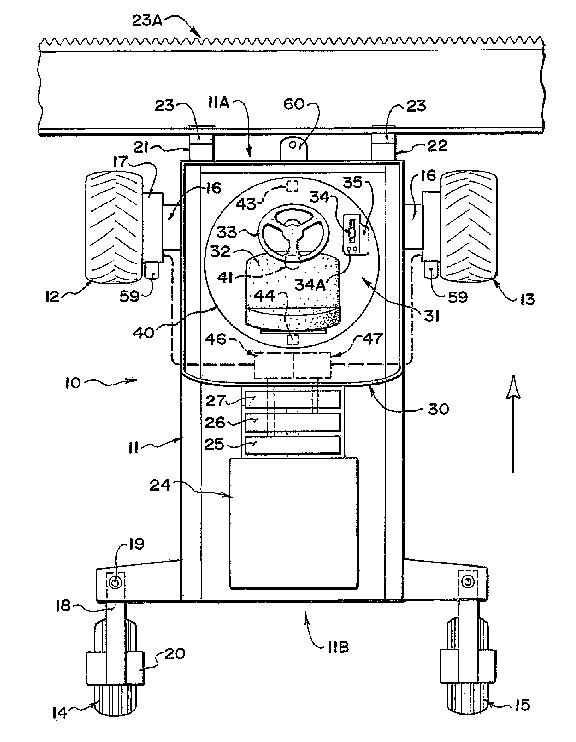
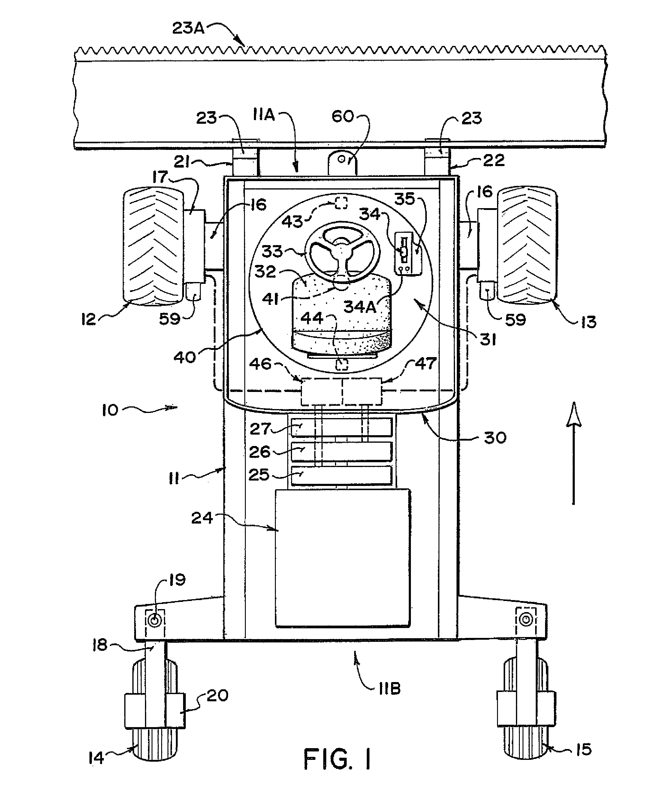
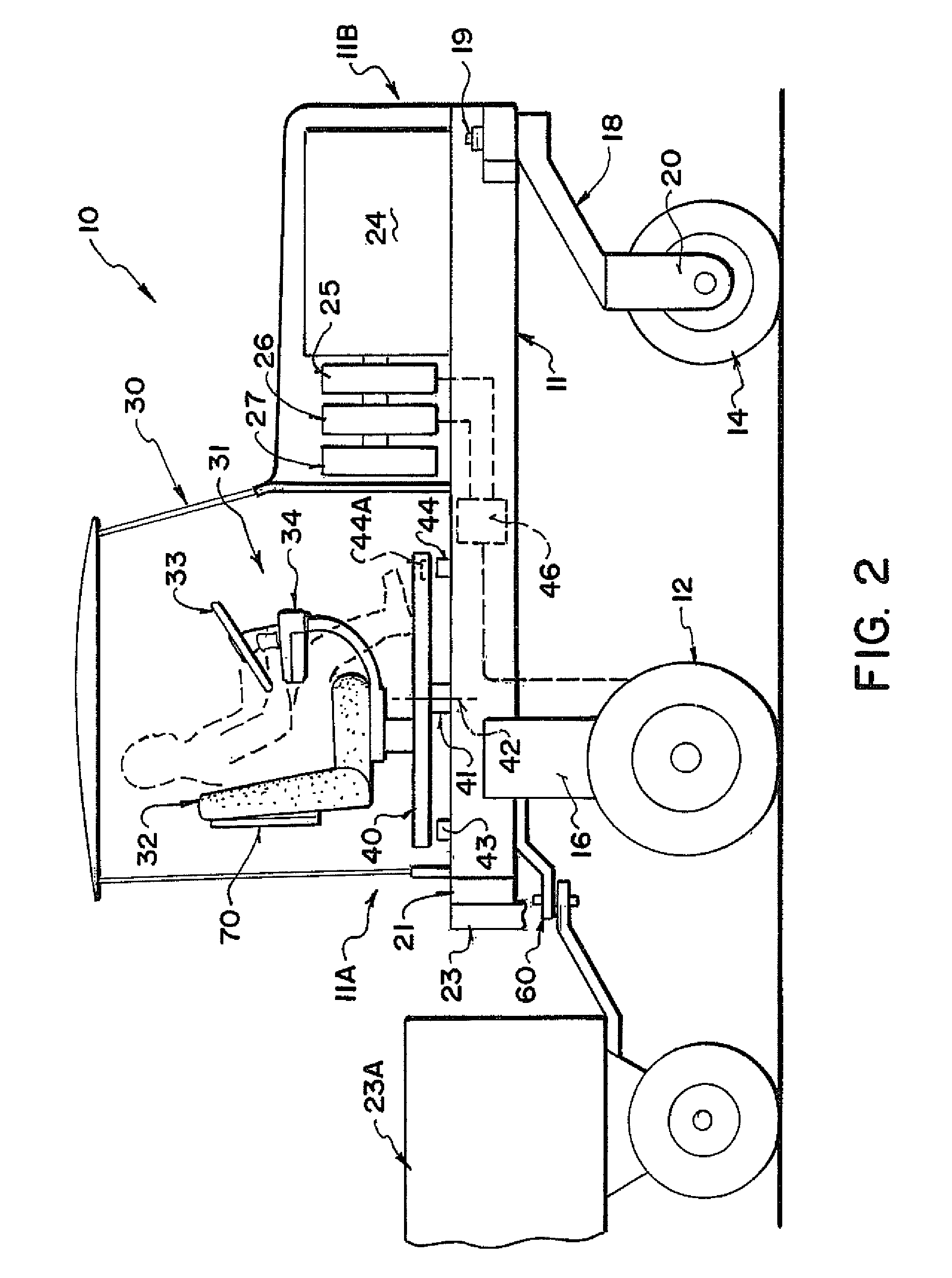
[0058]A swather tractor generally indicated at 10 includes a frame 11 which is carried on a first pair of driven ground wheels 12 and 13 and on a second pair of non-driven castor wheels 14 and 15. The driven wheels 12 and 13 are mounted on suitable supports 16 which support the ground wheels from the frame 11. The driven ground wheels 12 and 13 are each driven by a hydraulic motor 17 carried on the support 16 which receives hydraulic fluid under pressure from a supply line and drives the ground wheel at a rate of rotation dependant upon the rate of flow of the hydraulic fluid.

[0059]The wheels 14 and 15 are mounted on conventional castors 18 which swivel about a castor pin 19. The ground wheels 14 and 15 are non driven and are simply mounted in a supporting bracket 20 which can pivot around the castor pin 19 so that the castor wheels follow the movement of the vehicle as controlled by the driven wheels 12 and 13. Thus the speed of the vehicle over the ground is controlled by the rate...


PUM


Abstract

A tractor has hydraulically driven wheels at a cab end and castor wheels at an engine end. It can be driven cab forward in a working mode with a header on the forward end. It is rotated to engine forward in the transport position for more stable higher speed travel. The driven wheels are driven by hydraulic motors each having their own drive pump the output of which is controlled by a cam plate. There is provided an automatic steering system having a guidance controller arranged to receive GPS position information and feed back signals and to generate output for controlling a hydraulic control valve for controlling flow in hydraulic fluid for a double acting hydraulic control cylinder arranged to actuate pivotal movement of the steering link member independently of the steering shaft.

Description

[0001]This invention relates to an automatic steering system for a hydraulically driven tractor of the type, commonly but not necessarily used as a swather tractor, which is supported on a pair of hydraulically driven wheels and a pair of castor wheels and steered by a differential speed between the driven wheels.BACKGROUND OF THE INVENTION[0002]Hydrostatically steered vehicles have been available for many years and their application to windrowers has been significant. There has been a limit to the transport speed of these windrowers due to instability at high speed with the drive wheels ahead of the castor wheels (cab forward). Higher speeds on the road allow the user to cover large distances without the use of trailers and tow vehicles.[0003]In co-pending application filed Apr. 28, 2005, Ser. No. 11 / 116,418 published as 2006 / 0201732 and Canadian application filed Apr. 27, 2005, Ser. No. 2,513,614 and assigned to the present assignee is shown a machine in which the machine travels ...

Claims


Application Information

Patent Timeline
Patent Type & Authority Patents(United States)
IPC IPC(8): B62D11/02
CPCA01B69/008B62D11/001B62D1/02
Inventor DUNN, JAMES THOMASOTTO, PHILIP J.SNIDER, GEOFFREY U.
Owner MACDON INDS
Why Eureka
Try Eureka