Spacer for circuit boards

a technology of spacers and circuit boards, which is applied in the direction of printed circuit manufacturing, electrical apparatus construction details, casings/cabinets/drawers, etc., can solve the problems of increasing product cost, increasing the time necessary to complete the final assembly, and requiring multiple parts, so as to achieve correct positioning, reliably connected, and simple and inexpensive structure

Inactive Publication Date: 2010-05-25
YAZAKI NORTH AMERICA
View PDF18 Cites 15 Cited by
  • Summary
  • Abstract
  • Description
  • Claims
  • Application Information

AI Technical Summary

Benefits of technology

[0006]Another object of the invention is to keep the circuit boards properly spaced, correctly positioned, and reliably connected such that the electrical components mounted on the circuit boards do not interfere with each other and the circuit boards are not damaged during shipping and handling.
[0007]A further object of the invention is to provide this retainer / spacer as a straightforward and inexpensive structure for ease of manufacture and quick assembly with the circuit boards.

Problems solved by technology

This increases the time necessary to complete the final assembly and requires multiple parts, including fasteners and separate spacers.
Product cost increases with the number of parts, and the chance of losing or misplacing necessary parts creates additional production problems and expense.
Assembly line inefficiencies can occur if the circuit boards are not quickly and properly positioned relative to each other.
Though interlocking elements for securing multiple circuit boards together do exist in the art, they are generally not compact and often not reliable.

Method used


Image

  • Spacer for circuit boards
  • Spacer for circuit boards
  • Spacer for circuit boards

Examples


Embodiment Construction

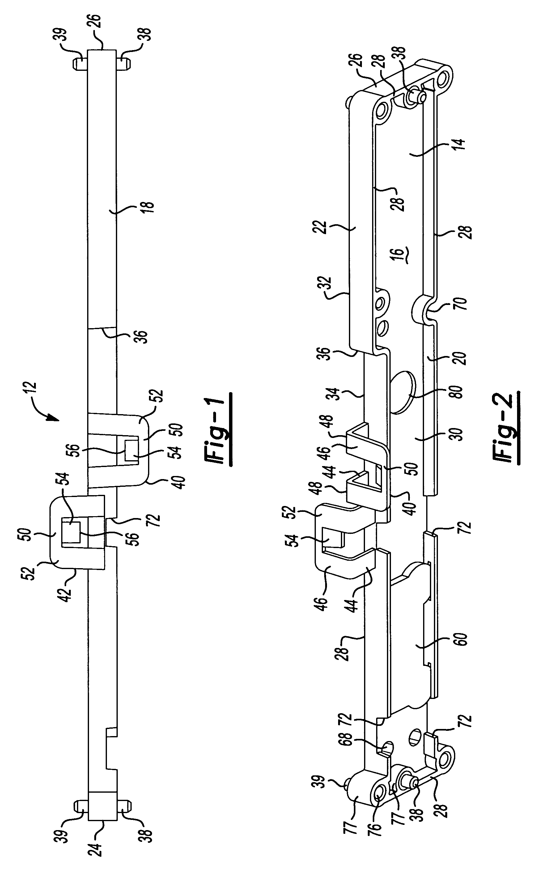
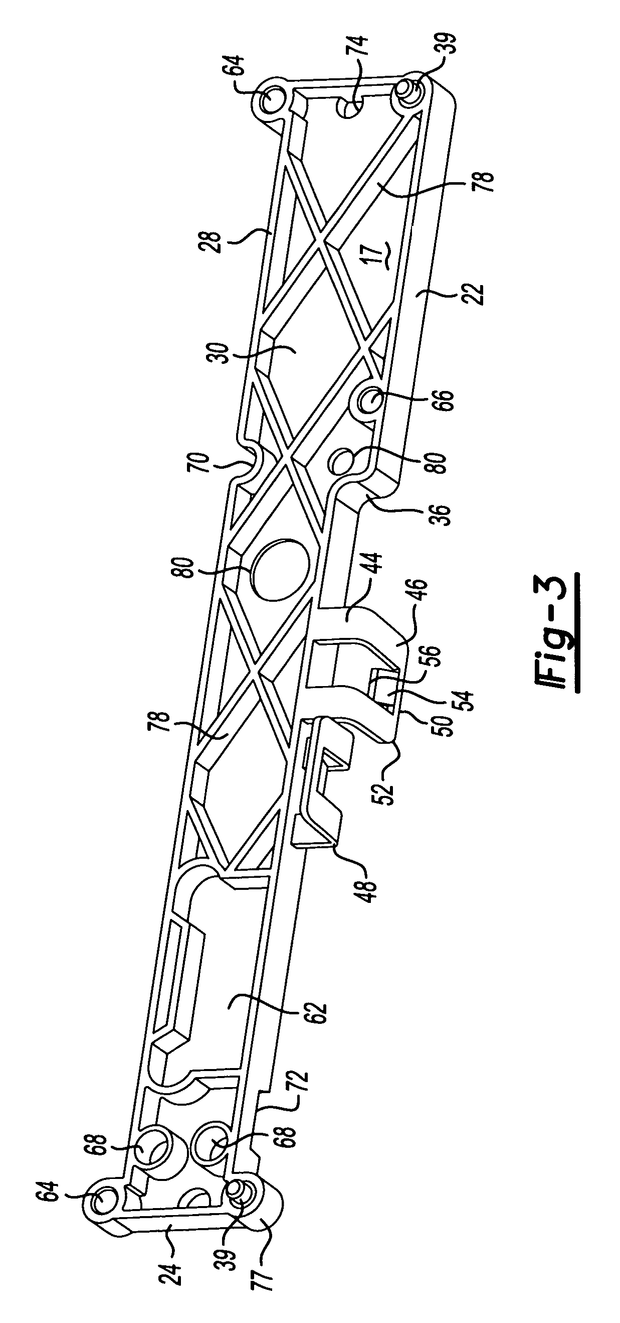
[0016]Referring now to FIGS. 1-3, a retainer or spacer 12 according to the present invention is molded in one-piece from a suitable, electrically non-conductive plastic such as Polypropylene. The spacer 12 is generally rectangular and has a base 14 with a first generally flat side 16 (FIG. 2) and a second, opposite facing, substantially flat side 17 (FIG. 3). The base 14 is surrounded or bounded by a frame 18 having a first outer perimeter wall 20 and a second, opposite outer perimeter wall 22 joining a first end wall 24 and a second end wall 26. The frame 18 has edges forming a raised peripheral rim 28 around each side of the base. The frame 18 is wider than the base 14 such that a recess 30 of predetermined depth is formed within the bounds of the peripheral rim 28 above each side of the base.

[0017]The spacer frame 18 has a shorter, wider portion 32 extending inward from the second end wall 26 and a longer, narrower portion 34 extending inward from the first end wall 24. The wider...


PUM


Abstract

A spacer or retainer secures two circuit boards in a back-to-back configuration. The spacer has opposite first and second sides, each having a peripheral rim against which the circuit boards fit. Each side is recessed to a depth enabling any component terminals or connections from rear surfaces of the circuit boards to be received in the recesses. Pins on ends of the spacer are received in apertures in the circuit boards to guide the circuit boards into position on the spacer. Two clips are positioned next to each other on one wall forming the peripheral rim. Each clip extends beyond an opposite side, and the clips have resilient tabs biased to press the circuit boards against the rims. The circuit boards are connected by electrical wire extending around an opposite wall of the peripheral rim. The spacer and circuit boards form a subassembly, such as for a vehicle instrument cluster.

Description

BACKGROUND OF THE INVENTION[0001]1. Field of the Invention[0002]The invention relates to a combined spacer and retainer for properly spacing and retaining two circuit boards in a subassembly without the need for using screws or other time-consuming fastening methods.[0003]2. Discussion of Related Art[0004]Typical electronic assemblies requiring multiple circuit boards often secure the circuit boards together by using screws or bolts. This increases the time necessary to complete the final assembly and requires multiple parts, including fasteners and separate spacers. Product cost increases with the number of parts, and the chance of losing or misplacing necessary parts creates additional production problems and expense. Assembly line inefficiencies can occur if the circuit boards are not quickly and properly positioned relative to each other. Though interlocking elements for securing multiple circuit boards together do exist in the art, they are generally not compact and often not r...

Claims


Application Information

Patent Timeline
Patent Type & Authority Patents(United States)
IPC IPC(8): H05K7/12
CPCH05K7/142
Inventor SALINAS FOX, VICTOR HUGOMASUDA, AKIRA
Owner YAZAKI NORTH AMERICA
Why Eureka
Try Eureka