Cutting device for pipelines

a technology for pipelines and cutting devices, applied in sewer pipelines, pipe laying and repair, tube shearing machines, etc., can solve problems such as discontinuous cutting operations, and achieve the effect of large longitudinal extent and smooth movemen

Active Publication Date: 2010-06-01
TRACTO TECHN
View PDF11 Cites 10 Cited by
  • Summary
  • Abstract
  • Description
  • Claims
  • Application Information

AI Technical Summary

Benefits of technology

[0011]The present invention resolves prior art problems by the provision of the basic body which is moved through a pipeline to be cut and includes at least one cutting or perforating element to cut the pipeline in the longitudinal direction or to weaken the pipe material. Thus, the cutting operation taking place discontinuously. As a result, generation of uncontrolled cracks when cutting and resultant formation of fragments are reduced.
[0018]The advantageous action of such a cutting roller is allowed by a simple and cost-effective construction. Other cutting elements which enable the pipeline to be cut discontinuously in the longitudinal direction may, for example, involve a cutting knife being alternately radially deflected and retracted again. Thermal and laser cutting processes are also possible.
[0023]The necessary spacing between the two basic bodies, and thus the two cutting elements, may also be produced for example by fastening a linkage section, as also used for the pulling linkage, between the two basic bodies. The articulated connection of the two basic bodies with one another makes it possible to ensure that the cutting device according to the invention, having a large longitudinal extent in some cases, can be moved smoothly without jamming within a pipe run which may not be completely rectilinear.
[0024]The modular structure of the cutting device with basic bodies connected via quick couplings and having one or more respective cutting or perforating elements is also advantageous for mounting or demounting in narrow pits.
[0027]In order to counter the occurrence of repair clamps, the cutting device according to the invention may comprise a third cutting or perforating element which follows the second cutting or perforating element and protrudes beyond the latter in terms of its radial extent. Its radial extent is preferably matched to the external dimensions of conventional repair clamps for pipelines. Recourse is preferably once again had to a cutting roller and / or a cutting knife as the third cutting element on account of its simple construction.

Problems solved by technology

Thus, the cutting operation taking place discontinuously.

Method used


Image

  • Cutting device for pipelines
  • Cutting device for pipelines
  • Cutting device for pipelines

Examples


Embodiment Construction

[0036]Throughout all the Figures, same or corresponding elements are generally indicated by same reference numerals. These depicted embodiments are to be understood as illustrative of the invention and not as limiting in any way. It should also be understood that the drawings are not necessarily to scale and that the embodiments are sometimes illustrated by graphic symbols, phantom lines, diagrammatic representations and fragmentary views. In certain instances, details which are not necessary for an understanding of the present invention or which render other details difficult to perceive may have been omitted.

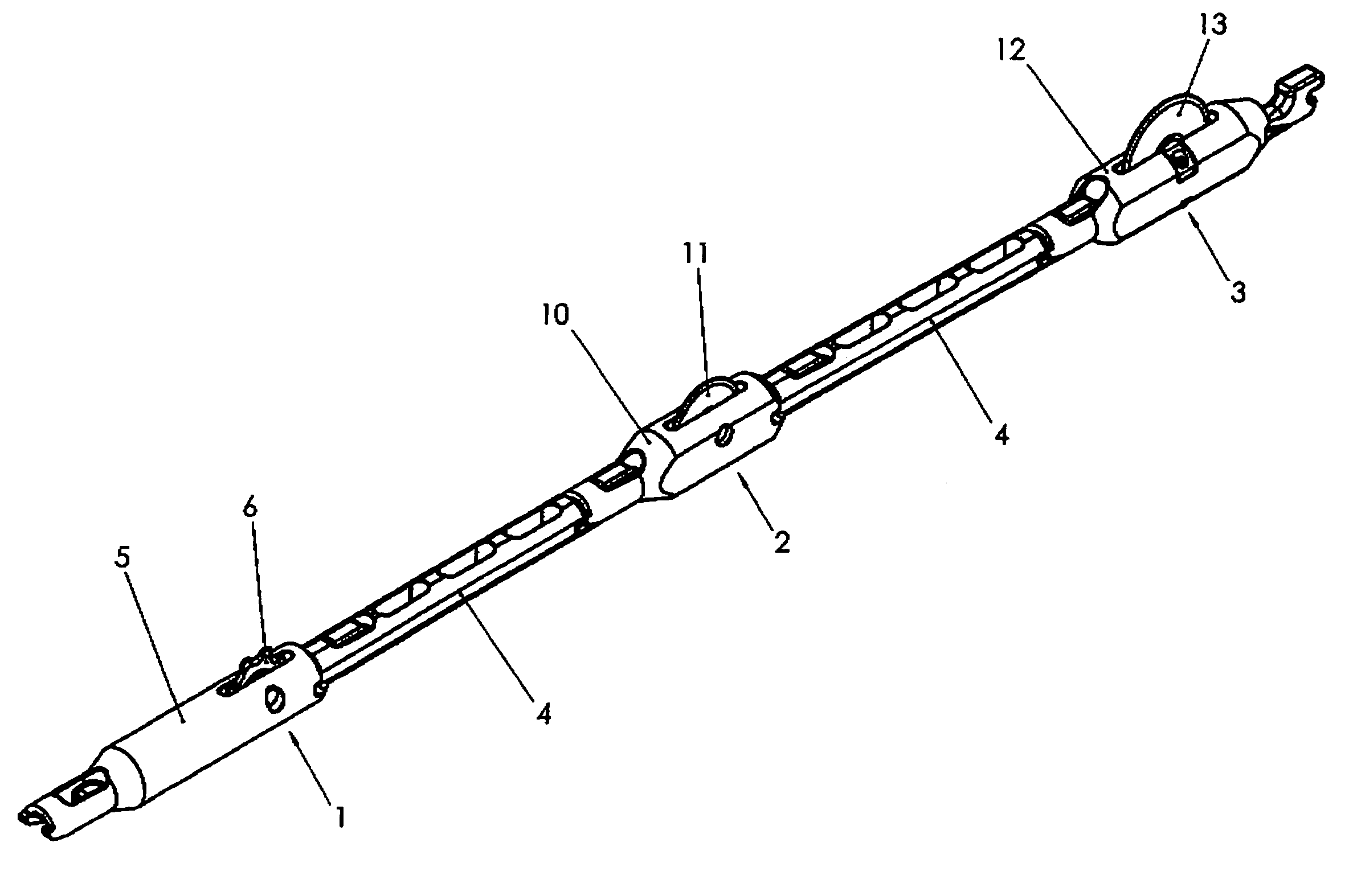
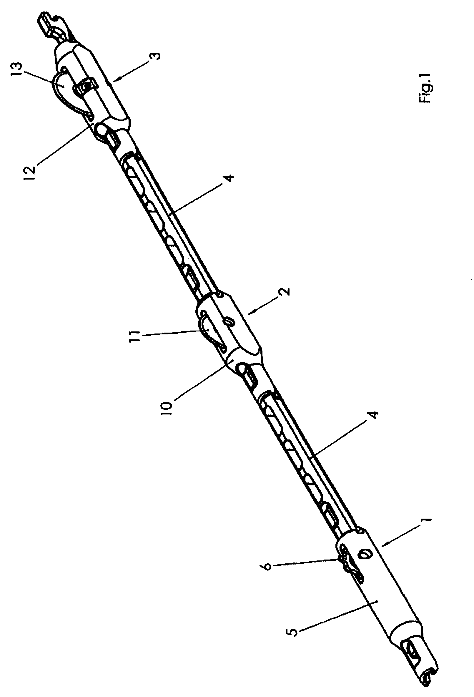
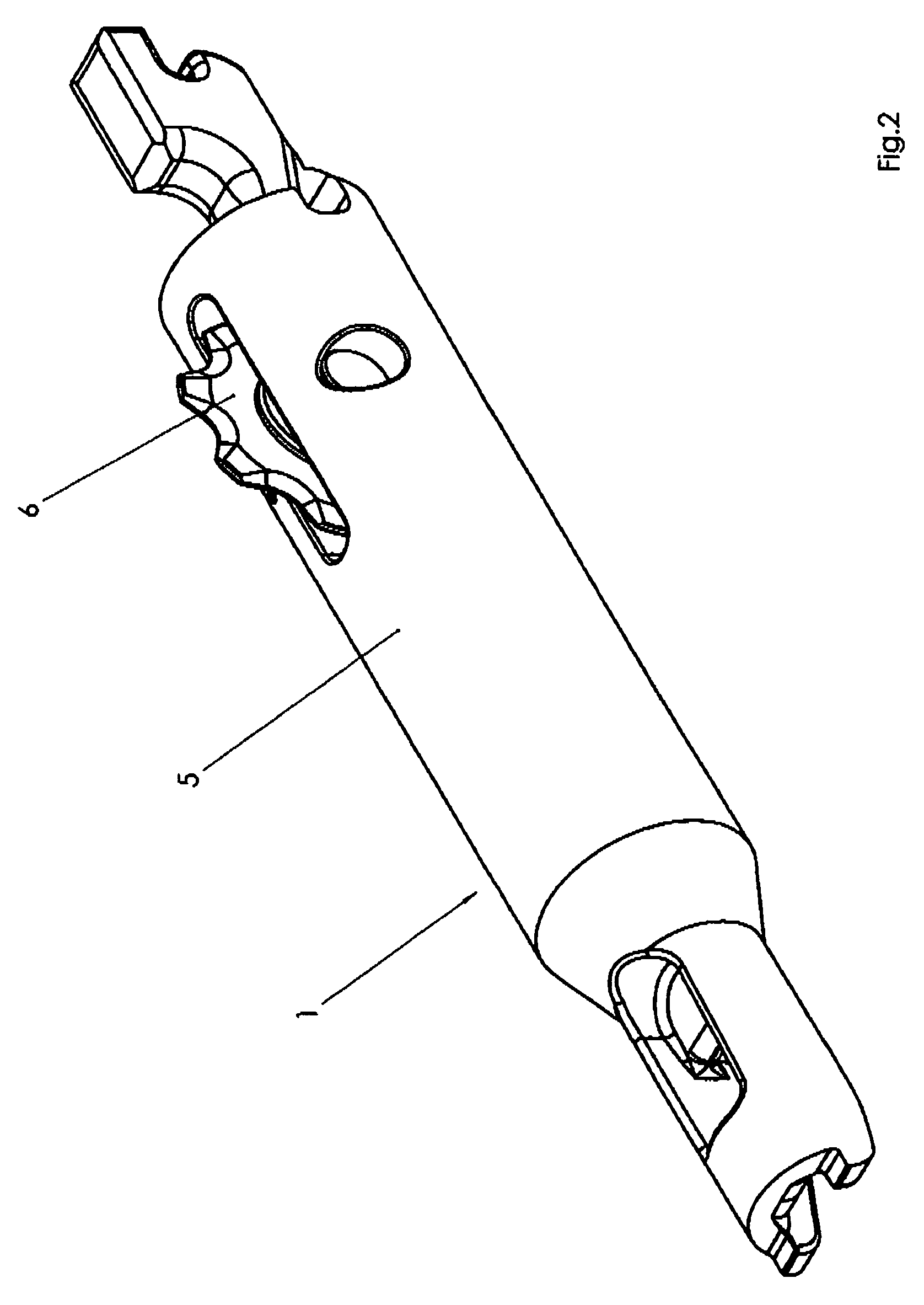
[0037]Turning now to the drawing, and in particular to FIG. 1, there is shown a cutting device according to the present invention, essentially including three cutting element modules 1, 2, 3 which are connected to one another via short linkage sections 4. The first cutting element module 1 has a cross-sectionally circular, elongate basic body 5 whose two ends are respectively ...


PUM

PropertyMeasurementUnit
diameteraaaaaaaaaa
areaaaaaaaaaaa
distanceaaaaaaaaaa

Abstract

A cutting device for cutting or bursting a pipeline includes a basic body having at least one cutting or perforating element, wherein the cutting or perforating element discontinuously cuts the pipeline in the longitudinal direction or at least discontinuously weakens the pipe material.

Description

CROSS-REFERENCES TO RELATED APPLICATIONS[0001]This application claims the priority of German Patent Application, Serial No. 10 2005 001 222.1-14, filed Jan. 10, 2005, pursuant to 35 U.S.C. 119(a)-(d), the content of which is incorporated herein by reference.BACKGROUND OF THE INVENTION[0002]The invention relates to a cutting device for cutting or bursting pipelines.[0003]Nothing in the following discussion of the state of the art is to be construed as an admission of prior art.[0004]A cutting device is disclosed for example in German Pat. No. DE 198 31 190 C1. The cutting device is pulled via a linkage through a pipeline to be cut and provided on one side of an elongate basic body with three rotatably mounted cutting rollers arranged in a line and at a distance from one another. Situated opposite each of the cutting rollers is a support roller which is used to bear the transverse forces on the pipe shell caused by the cutting rollers.[0005]The first cutting roller as seen in the pull...

Claims


Application Information

Patent Timeline
Patent Type & Authority Patents(United States)
IPC IPC(8): B23D21/06E21B29/00
CPCB23D21/02B26D3/001Y10T83/04B23D21/14
Inventor KOCH, ELMARKOPER, MARTINPUTTMANN, FRANZ-JOSEF
Owner TRACTO TECHN
Why Eureka
Try Eureka