
Work table for an automatic machine for cutting leathers and the like

a work table and automatic technology, applied in the field of automatic systems, can solve the problems of limiting the production rate of the above machine, cyclical and limited by the operators' manual operations, and difficult cutting of the leather p on the work table l, so as to increase the production rate of the machine, the effect of saving tim

Active Publication Date: 2010-06-01
TESEO SPA
View PDF11 Cites 2 Cited by
  • Summary
  • Abstract
  • Description
  • Claims
  • Application Information

AI Technical Summary

Benefits of technology

[0019]The object of the resent invention is to propose a work table of an automatic machine for cutting leathers and the like, which allows the operators to control, to spread the tanned leathers on the surface and to remove the cutting products in a practical, functional and easy way, thus saving time, which results in a considerable increase of the machine production rate.

Problems solved by technology

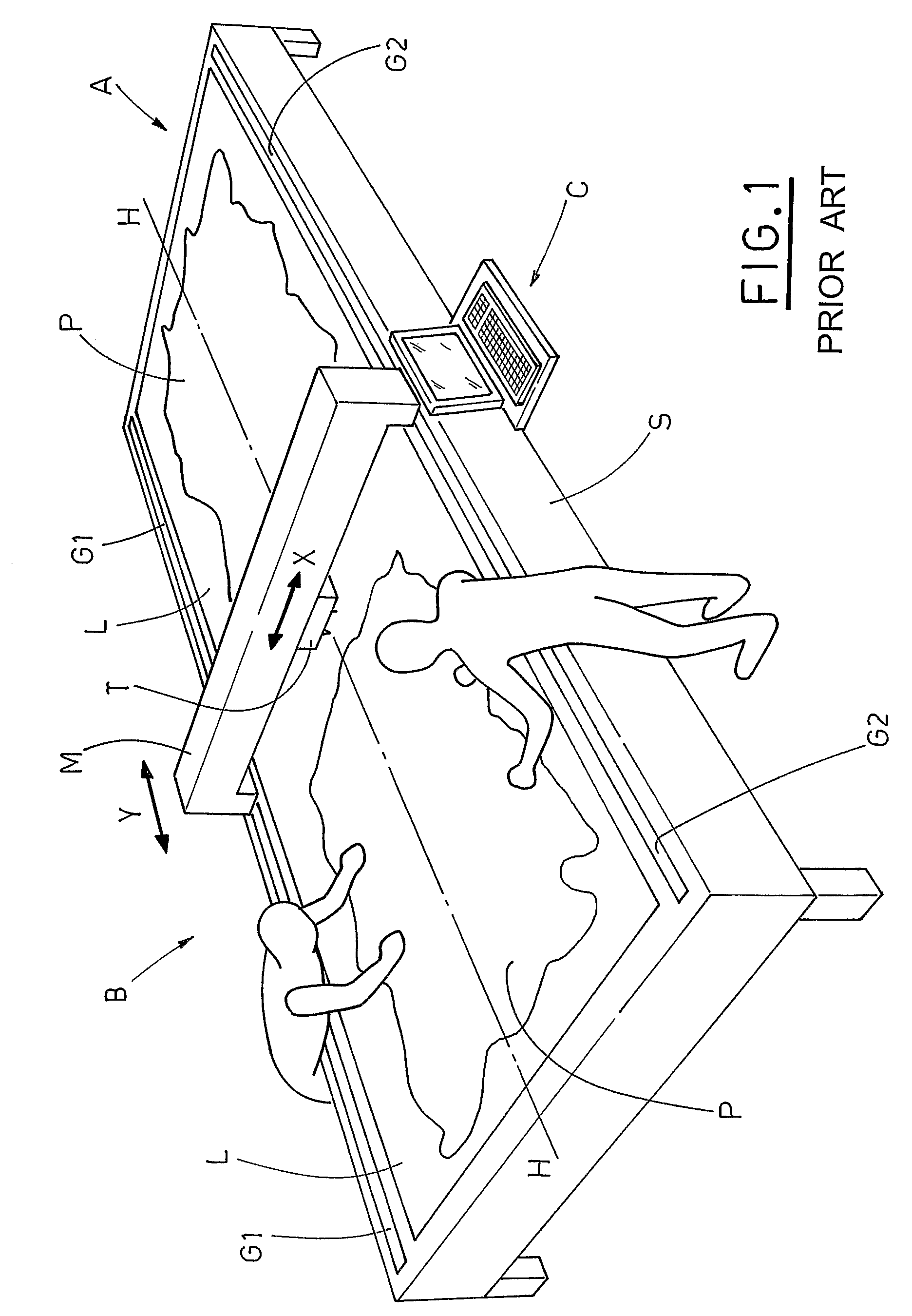
Therefore, the processing of tanned leather, described in its significant steps, is cyclical and limited by the operators' manual operations, actually longer than the automatic cutting operations.
In fact, the spreading of a leather P on the work table L and the subsequent removal of the cutting products is very difficult, due to the limited access to some portions of the leather P, situated near the longitudinal axis H, which makes the operator climb up to the surface L or use a suitable structure.
A further limit to the production rate of the above machine derives from the quality control of the leathers to be cut, which requires looking for possible imperfections on the tanned leather, and subsequent marking of faulty areas.

Method used


Image

  • Work table for an automatic machine for cutting leathers and the like
  • Work table for an automatic machine for cutting leathers and the like
  • Work table for an automatic machine for cutting leathers and the like

Examples


Embodiment Construction

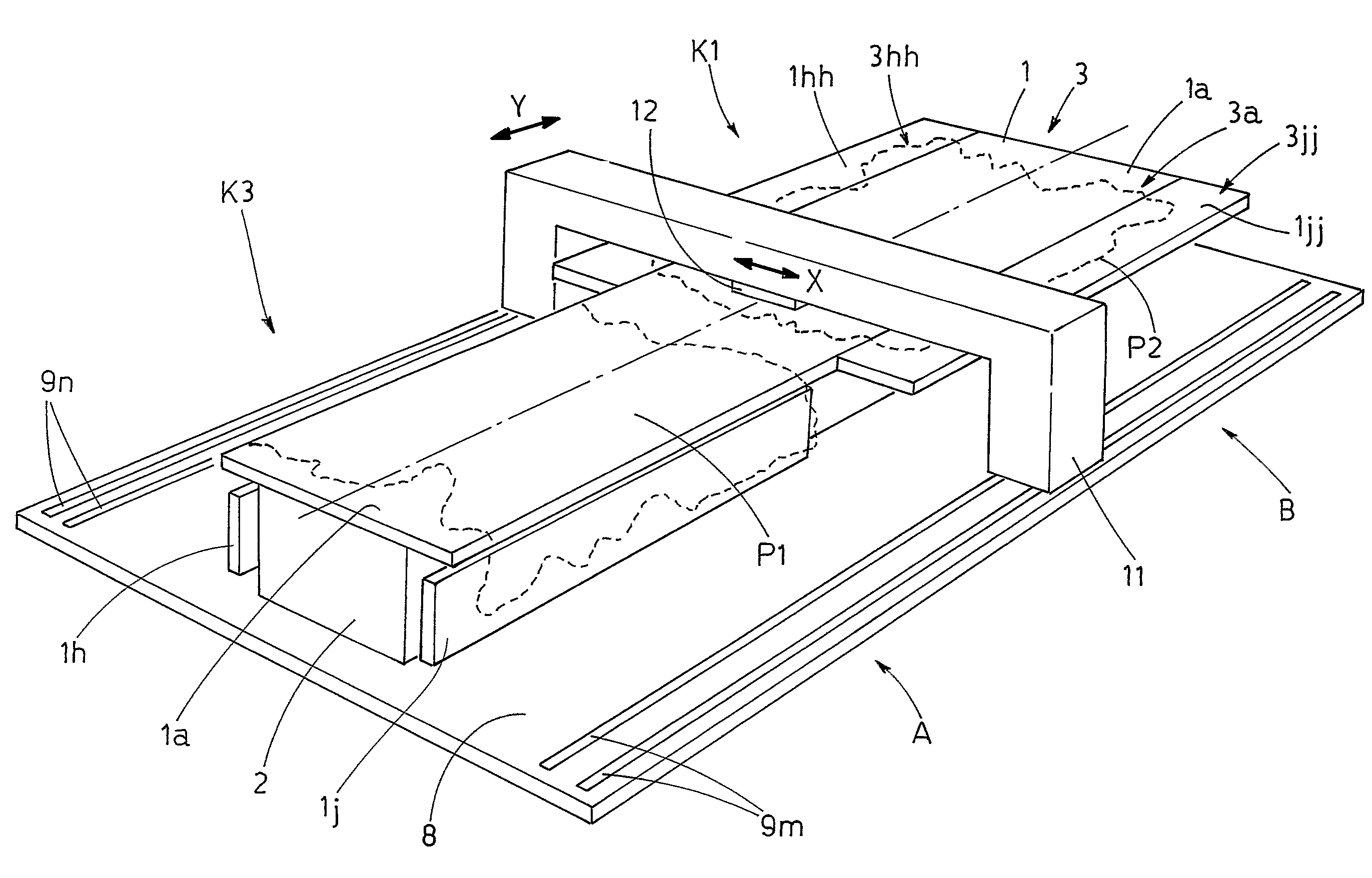
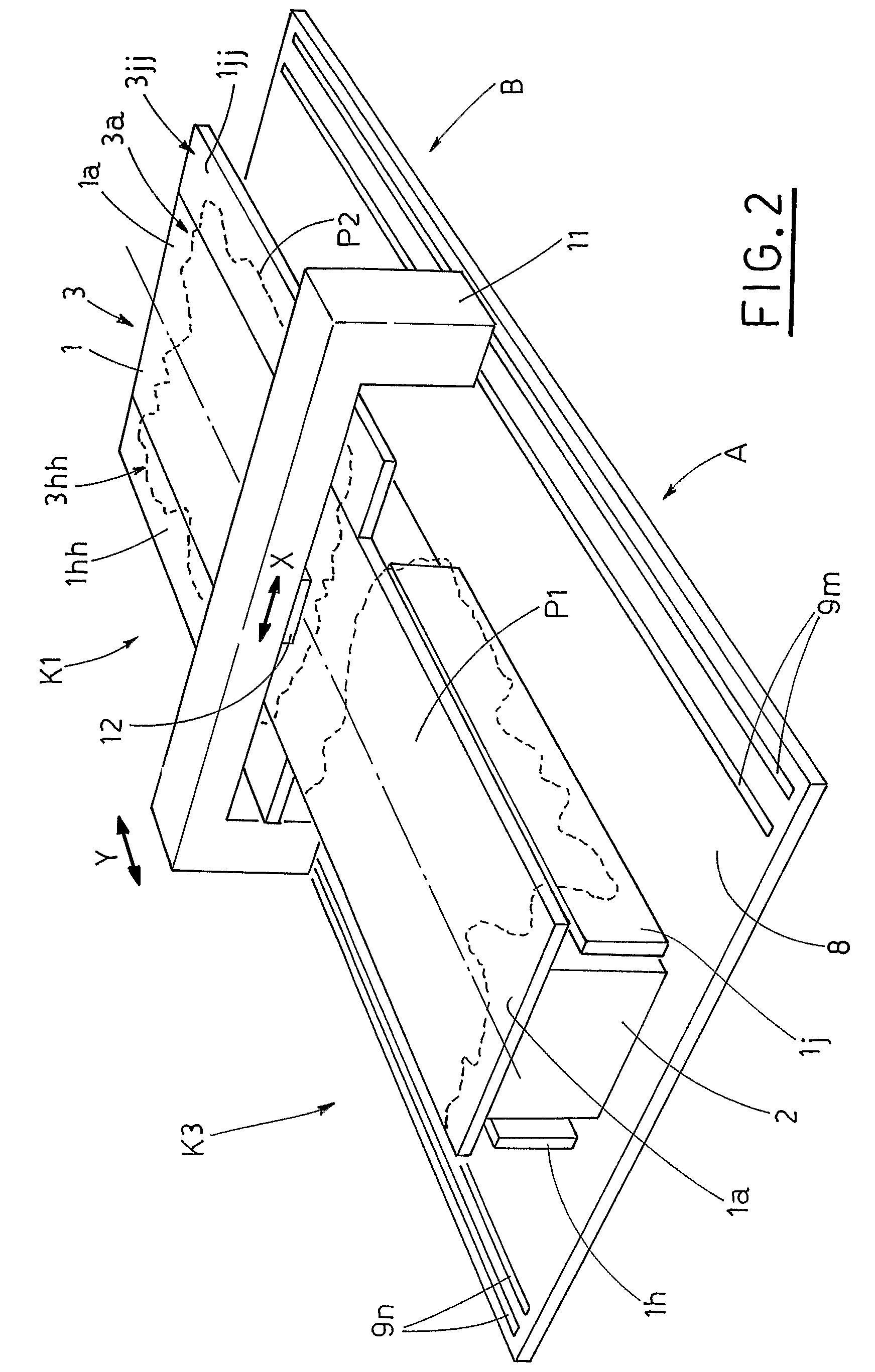
[0030]With reference to the enclosed Figures, the referenced number 1 indicates a work table, supported by a fixed structure 2. A suction effect is obtained by a plurality of holes, not shown, made in the work table and connected to a source of vacuum, likewise not shown, as known: see e.g. the European Patent EP 1.178.120 of the Applicant.

[0031]FIG. 2 shows a preferred embodiment of the work table 1, which includes a central body 1a, defined by a rectangular plate 1a, which has an active, flat surface 3a and four lateral portions 1h, 1hh, 1j, 1jj, arranged in pairs, situated at the opposite ends of the body 1a and defining plates featuring active surfaces 3h, 3hh, 3j, 3jj, respectively.

[0032]The latter, in some work configurations, are aimed at aligning with the central body 1a, defining a single, coplanar active surface 3, obtained by the joining of the active surfaces 3a, 3h, 3hh, 3j, 3jj.

[0033]The work table 1 has two symmetry planes, a longitudinal one and a transversal one.

[0...


PUM

PropertyMeasurementUnit
angleaaaaaaaaaa
dimensionaaaaaaaaaa
reduced dimensionaaaaaaaaaa

Abstract

A work table for an automatic machine for cutting leathers and the like, includes a plurality of holes opening outwards and communicating with a vacuum source, to make portions of leathers to adhere to the active surface (3) of the work table (1). The work table (1) includes a central body (1a), supported by a fixed structure (2). At least one lateral portion (1h, 1j), connected to the fixed structure (2), is moved by first motion means (10h, 10j) between at least one work configuration (K1), in which its active surface (3h, 3j) is aligned with the active surface (3a) of the central body (1a), to define the active surface (3) of the work table (1), and a rest configuration (K2) of reduced dimension, in which the active surfaces (3a, 3h, 3j) of the central body (1a) and the lateral portion (1h, 1j) are arranged at an angle with respect to each other.

Description

FIELD OF THE INVENTION[0001]The present invention relates to automatic systems for cutting valuable tanned leathers and the like.BACKGROUND OF THE INVENTION[0002]The known system for cutting fabric, synthetic materials and leathers, can be classified in accordance with the cutting technique, providing for the use or non-use of die cutters, i.e. tools, having a cutting relief or edge forming a given shape, and cuts a material giving it the contour matching the cutting relief or edge.[0003]Die cutting machines, which mount such cutter systems, known also as die cutting machines, are widespread in the industrial manufacturing field and use, as specified, cutting means, which are shaped according to the shape to be obtained, and which must be substituted for each new production lot (size changeover).[0004]In time, the above systems have been substituted by the ones cutting without die cutters, which work with a continuous movement of a cutting tool along the contour of the piece to be o...

Claims


Application Information

Patent Timeline
Patent Type & Authority Patents(United States)
IPC IPC(8): C14B1/26
CPCC14B17/04C14B5/00B26D7/015B26D7/018B26D7/20
Inventor GALLUCCI, GIANNI
Owner TESEO SPA
Learn More