High strength steel cylinder liner for diesel engine

a high-strength steel and cylinder technology, applied in the direction of cylinders, machines/engines, mechanical equipment, etc., can solve the problems of limiting the thinness of the cast iron liner, and reducing the performance of the engine, so as to reduce the corrosive effects of the egr environment, the effect of high strength and greater bore diameter

Inactive Publication Date: 2010-06-01
FEDERAL MOGUL WORLD WIDE LLC
View PDF37 Cites 27 Cited by
  • Summary
  • Abstract
  • Description
  • Claims
  • Application Information

AI Technical Summary

Benefits of technology

[0009]Although the present invention has application outside of diesel engines having a certain amount of exhaust gas recirculated (EGR) back to the cylinder of the engine, it is particularly favorable in this environment for its resistance to the corrosive effects of an EGR environment. The present invention offers a solution to the limitations of cast iron liners in EGR applications, as well as offering high strength solutions for non-EGR engines as well, particularly connection with top and mid-stop liners by fabricating the liners out of steel rather than cast iron. Steel is considerably harder than cast iron and lacks the free graphite which is attributable in part to the undesirable wear and cavitation discussed above. Steels that can be used for the present invention include hardenable carbon and high chrome steels. The liners are manufactured with a texture roughness descriptor, TRD=5Rvk(100−Mr2) of between 50 and 400 μm. This texture can be applied over the entire inner running surface of the liner or to just an upper portion within 30-40 mm from the top of the liner in the in the region of the return stroke of the top piston ring. The liners are preferably thin-walled with a ratio of compound average liner section thickness to bore diameter in the range of 1.5 to 4 percent. This thin wall section allows for greater bore diameters in EGR engines, enabling engine manufacturers to gain additional cylinder displacement through use of relatively thin steel liners as favored over the traditional cast iron liners. Additionally, the inner wall of the liner is formed with a hardness that is within a spread of 10-20 Rc hardness of that of the piston rings.
[0010]The invention has the advantage of providing steel cylinder liners that are designed to operate in diesel engine applications. Steel liners are much less costly to produce than those of cast iron liners and can be made thinner so as to enable a larger cylinder displacement without having to increase the size of the engine block. Such thin, steel liners are capable of withstanding peak cylinder pressures of 220 bar and above without distortion, unlike their cast iron counterparts of comparable thickness. New engine platforms could be made smaller and lighter as the mass needed to ensure adequate support and strength of the steel liners would be less than that required for supporting conventional cast iron liners. Steel liners are less prone to breakage and are less prone to distortion as compared to traditional cast iron liners. Steel liners provide a good seal with the piston rings to enhance power and decrease emissions. Manufactures of such liners need not possess costly casting facilities needed for making cast iron liners and much of the machining equipment and processes presently used to finish cast iron liners can be used for the steel liners.

Problems solved by technology

For traditional cast iron liners, it has been demonstrated that under conditions of exhaust gas recirculation, or EGR, in which some of the exhaust gases are recirculated back into the cylinder for further combustion with the fresh fuel mix, the liners have shown accelerated wear in comparison to the same liners operating under non-EGR conditions.
In addition to the wear considerations of cast iron liners, the requirement for ever-increasing emissions regulation has the effect of reducing the performance of the engines.
However, there is a limit as to how thin a cast iron liner can be made and still function properly.
In particular, cast iron liners of thinner wall sections are prone to cavitation and distortion because the cast iron is a relatively porous material with free graphite present at the surface.
It is known to employ steel cylinder liners, but these are not know to be suitable designed for use in a heavy-duty wet linered diesel engine applications, where the temperatures are high and the peak cylinder pressures can reach 220 bar or more.

Method used


Image

  • High strength steel cylinder liner for diesel engine
  • High strength steel cylinder liner for diesel engine

Examples


Embodiment Construction

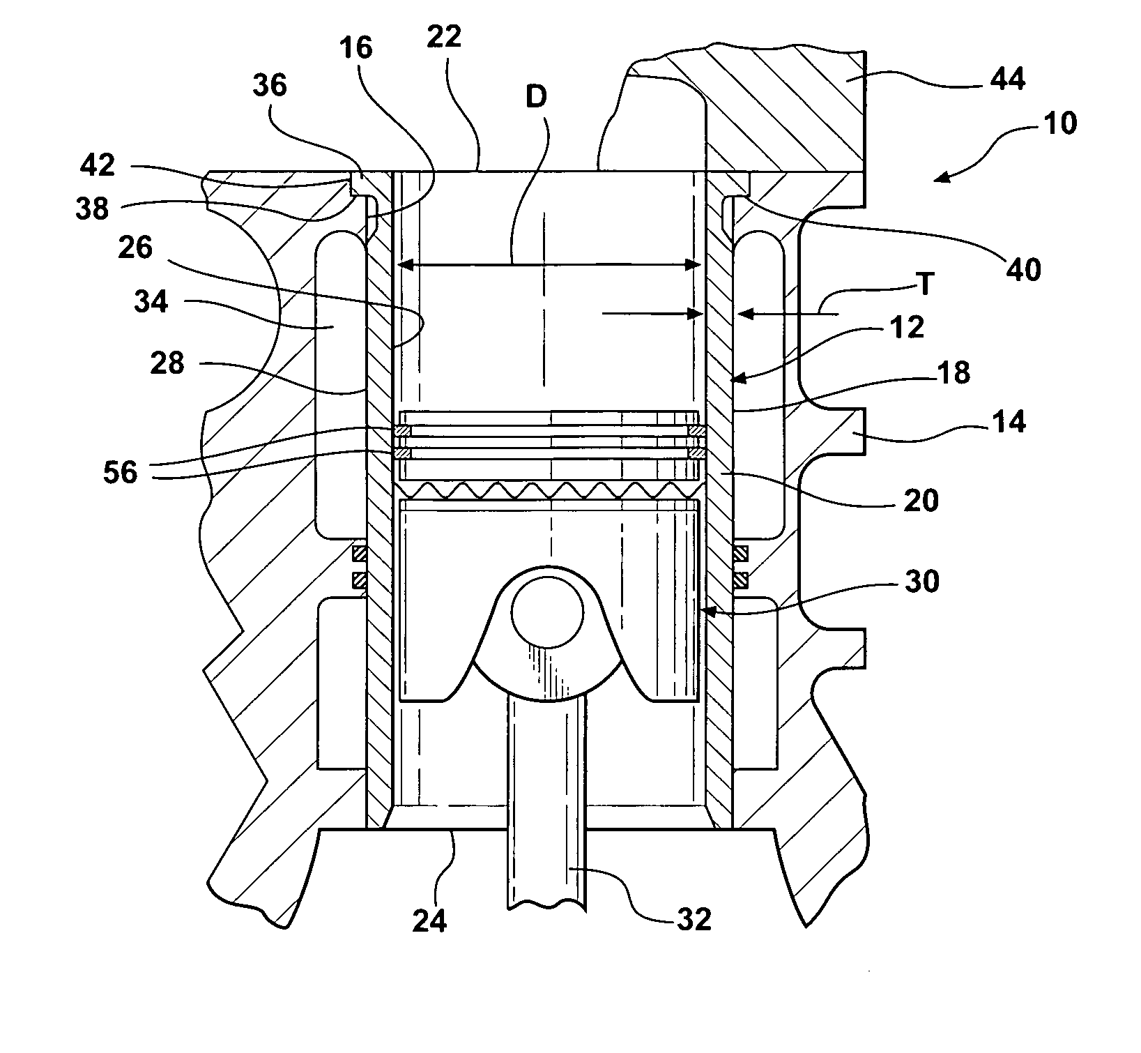
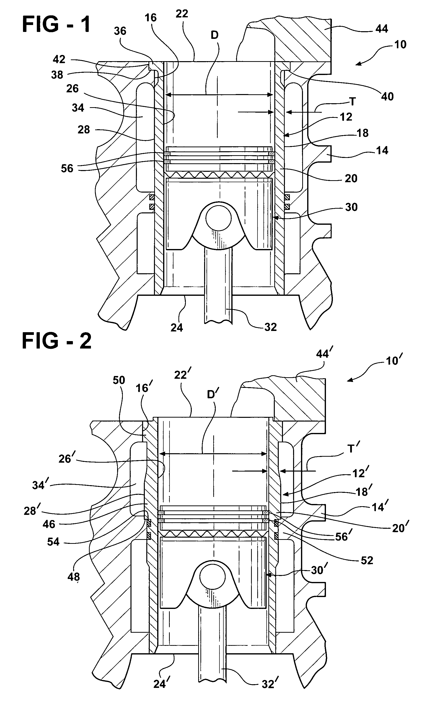
[0015]Turning now in more detail to the drawings, FIGS. 1 and 2 illustrate fragmentary cross-sectional views of a diesel engine 10, 10′ fitted with top-stop and mid-stop liners 12, 12′, respectively. The same reference numerals are used to designate like features of the embodiments of FIGS. 1 and 2, but those of FIG. 2 are primed.

[0016]The diesel engine 10, 10′ includes an engine block 14, 14′ formed with at least one piston bore 16, 16′ in which the liner 12, 12′ is removably mounted. The liners 12, 12′ have a generally cylindrical body 18, 18′ defined by a liner wall 20, 20′ of predetermined thickness. The liner 12, 12′ extends longitudinally between an upper or top end 22,22′ and an opposite bottom end 24, 24′ which are both open-ended. The wall 20, 20′ presents in inner running surface 26, 26′ and an outer surface 28, 28′. A piston 30, 30′ is received in the liner 12,12′ and is operatively coupled to a crank (not shown) of the engine 10, 10′ by a connecting rod 32,32′ for drivin...


PUM

PropertyMeasurementUnit
texture roughness descriptoraaaaaaaaaa
roughnessaaaaaaaaaa

Abstract

A diesel engine is fitted with a thin-walled wet liner fabricated of steel. The liner has a hardness that is within 10-20 Rc of the hardness of the piston rings carried on a piston within the liner. The inner surface of the liner is manufactured with a TRD=5Rvk (100−Mr2) of between 30 and 400 μm, and a compound liner thickness to bore diameter in the range of 1.5 to 4 percent.

Description

[0001]This application claims priority to U.S. Provisional Patent Application Ser. No. 60 / 553,265, filed Mar. 15, 2004.BACKGROUND OF THE INVENTION[0002]1. Technical Field[0003]This invention relates to cylinder liners for diesel engine applications.[0004]2. Related Art[0005]Historically, heavy duty diesel engines have employed replaceable cylinder liners made of various grades of cast iron. Cast iron is selected for its low production cost and good wear resistance due to the presence of free graphite at the running surface which acts as a lubricant. Increased wear resistance in the cylinder bore can be achieved by hardening the base cast iron alloy to create a martensitic microstructure.[0006]For traditional cast iron liners, it has been demonstrated that under conditions of exhaust gas recirculation, or EGR, in which some of the exhaust gases are recirculated back into the cylinder for further combustion with the fresh fuel mix, the liners have shown accelerated wear in comparison ...

Claims


Application Information

Patent Timeline
Patent Type & Authority Patents(United States)
IPC IPC(8): F02F1/00F02F1/10F02F1/16F02F1/20
CPCF02F1/20F02F1/16
Inventor AZEVEDO, MIGUELHIGHUM, ERIC
Owner FEDERAL MOGUL WORLD WIDE LLC
Why Eureka
Try Eureka