Method for manufacturing sand mold

a sand mold and manufacturing technology, applied in the field of sand mold production, can solve the problems of insufficient blow charge, clogging of ejecting nozzles, insufficient casing blow charge, etc., and achieve the effect of eliminating clogging and good sand mold

Active Publication Date: 2010-06-01
SINTOKOGIO LTD
View PDF8 Cites 34 Cited by
  • Summary
  • Abstract
  • Description
  • Claims
  • Application Information

AI Technical Summary

Benefits of technology

[0006]The purpose of the present invention is to provide a method of producing a good sand mold by eliminating the clogging and insufficient blow charge.

Problems solved by technology

However, if the volume after changed is large, the period of time for blow charging the molding sand, which is the period for supplying a compressed air to the surface of the molding sand, would be short and causes insufficient blow charging.
However, since in this conventional molding machine the compressed air is ejected under a high pressure to blow charge the molding sand well, the sand ejecting nozzles tend to be clogged, casing insufficient blow charge and necessitating troublesome cleaning of the nozzles.

Method used


Image

  • Method for manufacturing sand mold
  • Method for manufacturing sand mold
  • Method for manufacturing sand mold

Examples


first embodiment

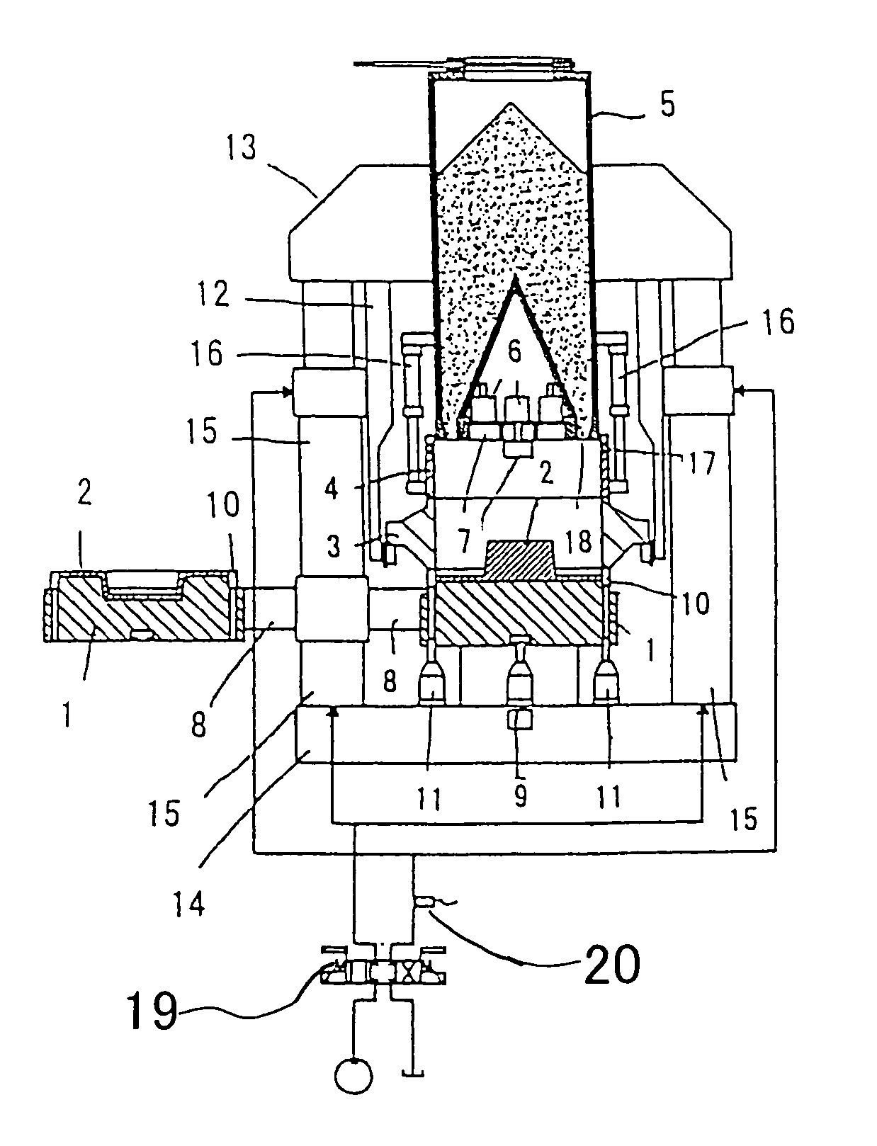
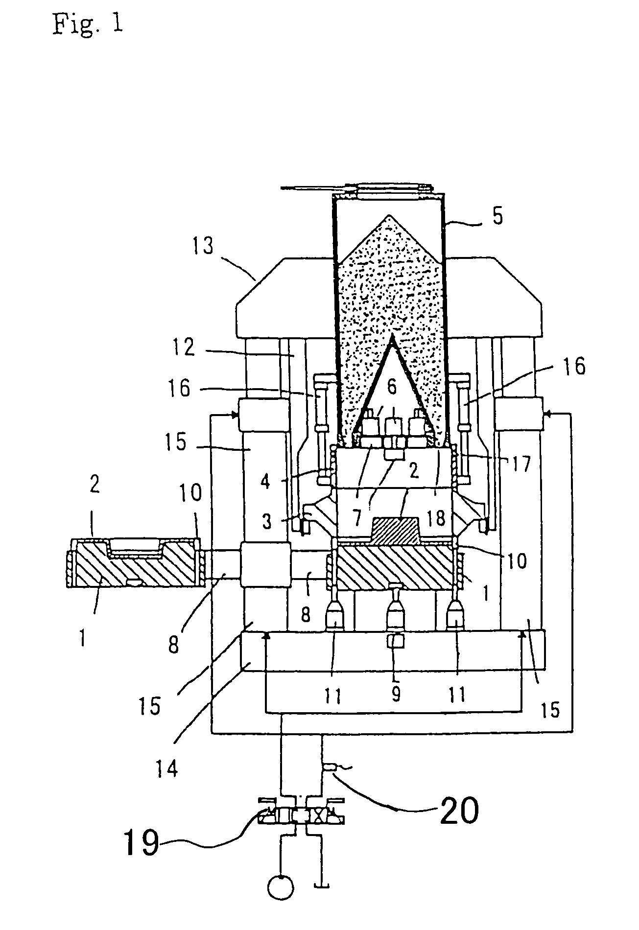
[0013]the method of the present invention is now explained in relation to a molding device shown in FIGS. 1 and 2 that uses the method. The molding machine shown in the drawings includes pattern plates 2, 2 each mounted on a transfer member 1 shaped as a surface plate, a molding flask 3 placed on the pattern plate 2, a filling frame 4 disposed for vertical moving above the flask 3, a sand blowing device 5 disposed for vertical moving above the filling frame 4 and having a lower end that slidably fits in the filling frame 4, and a plurality of squeeze feet 7, 7 mounded on the lower end of the sand blowing device 5, the squeeze feet are vertically moved by air cylinders 6, 6. There are two transfer members 1, 1 attached to arms 8, 8 that are horizontally rotatable, and each transfer member can be located in a position just below the filling frame 4 and can be away and out of the position. The transfer device 1 located at the positional is moved up to a designated position by allowing ...

second embodiment

[0023]the molding machine (for producing a cope and a drag that have no flask) used for carrying out the method of the present invention is now explained with reference to FIGS. 3 and 4. As shown in FIG. 3, the molding machine for producing a cope and a drag that have no flask includes a pair of upper and lower flask 33a, 33b, each formed with sand blow-in port in its side wall; a match plate 32, which can be inserted between the upper and lower flasks and has one or more vent holes therein; a molding sand squeeze mechanism 31 having upper and lower squeeze devices 34a, 34b provided with a plurality of upper and lower squeeze feet 37a and 37b, respectively, the mechanism 31 adapted to support and allow the upper and lower squeeze feet 37a and 37b to enter the upper and lower flasks 33a and 33b, respectively, from the sides opposite the other sides located at the match plate and adapted to support and allow the upper and lower flasks to reversely rotate to be located between a vertic...


PUM

PropertyMeasurementUnit
pressureaaaaaaaaaa
distanceaaaaaaaaaa
pressuresaaaaaaaaaa

Abstract

A method of producing a sand mold, comprising: after defining a mold space at least by a pattern plate, a flask, and a squeeze means, and after blow-charging molding sand held in a sand blowing device located above the mold space into the mold space by ejecting a first compressed air near sand ejecting ports of the sand blowing device thereby fluidizing the molding sand near the sand ejecting ports, while supplying a second compressed air to a surface of the molding sand held in the sand blowing device, moving the squeeze means toward the pattern plate, where in the pressure of the first compressed air and the period of time for supplying the first compressed air are adjusted to produce a good sand mold. To determine the period of time for ejecting the first compressed air, the distance of the movement of the squeeze feet toward the pattern plate is measured when the squeeze of the molding sand in the mold space is completed, and the difference between the measured distance and a target distance is calculated. The period is adjusted to be a shorter or lengthened one based on the result of the calculation.

Description

TECHNICAL FIELD[0001]This invention relates to a method of producing a sand mold.BACKGROUND ART[0002]A conventional method of producing a sand mold is disclosed in JP 2002-346697A, wherein after a mold space is defined by a flask placed on a pattern plate, a filling frame placed on the flask, and multiple squeeze heads inserted in the filling frame from above, and after the molding sand located at sand ejecting ports of a sand blowing device is fluidized by ejecting a compressed air to the molding sand at that location, a compressed air is supplied to the upper surface of the molding sand in the sand blowing device for a predetermined period of time to blow-charge the molding sand from the sand blowing device into the mold space, and the squeeze heads are lowered to squeeze the molding sand such that the level of the upper surface of the produced sand mold coincides with that of the flask.[0003]However, in the conventional method of producing a sand mold as configured above, the squ...

Claims


Application Information

Patent Timeline
Patent Type & Authority Patents(United States)
IPC IPC(8): B22C15/24B22C15/02B22C15/08
CPCB22C15/24B22C15/08B22C9/02
Inventor HIRATA, MINORUKANETO, KIMIKAZU
Owner SINTOKOGIO LTD
Why Eureka
Try Eureka