Panel mount light emitting element assembly

a technology of light emitting elements and assembly, which is applied in the direction of electrical equipment, lighting and heating equipment, coupling device connections, etc., can solve the problems of large overall size of the bezel used to mount the lamp assembly to the panel, difficult to package the light emitting assembly in extremely tight locations, and less pleasing aesthetically. , to achieve the effect of reducing size, easy disassembly and replacemen

Inactive Publication Date: 2010-06-01
TYCO ELECTRONICS CANADA
View PDF3 Cites 37 Cited by
  • Summary
  • Abstract
  • Description
  • Claims
  • Application Information

AI Technical Summary

Benefits of technology

[0007]Embodiments of the present disclosure include panel mounted light emitting assemblies having an internally mounted bezel. The internally mounted bezel allows mounting structures of reduced size, and thus, a smaller overall light emitting element assembly size.
[0008]In addition, the detachable bezel permits easy installation of the light emitting element assembly and easy disassembly for repair, replacement or upgrade of individual components of the light emitting element assembly.

Problems solved by technology

This makes the overall size of the bezel used to mount the lamp assembly to the panel very large.
The bulky external latch configurations make the assembly less pleasing aesthetically and also make it difficult to package the light emitting assemblies in extremely tight locations.
The minimization of space occupied by these light emitting assemblies is often an issue with applications, such as automotive interior lighting.

Method used


Image

  • Panel mount light emitting element assembly
  • Panel mount light emitting element assembly
  • Panel mount light emitting element assembly

Examples


Embodiment Construction

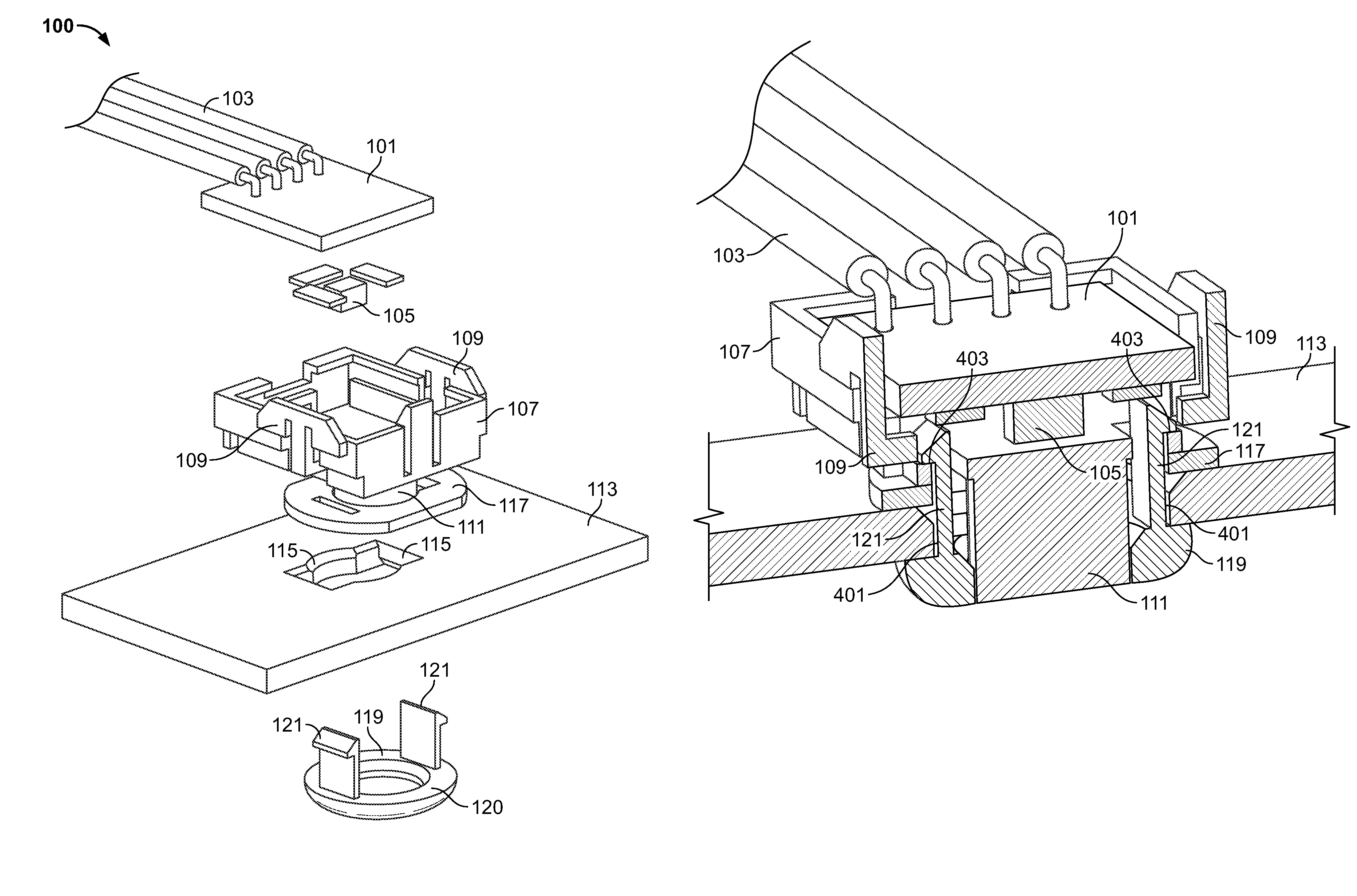
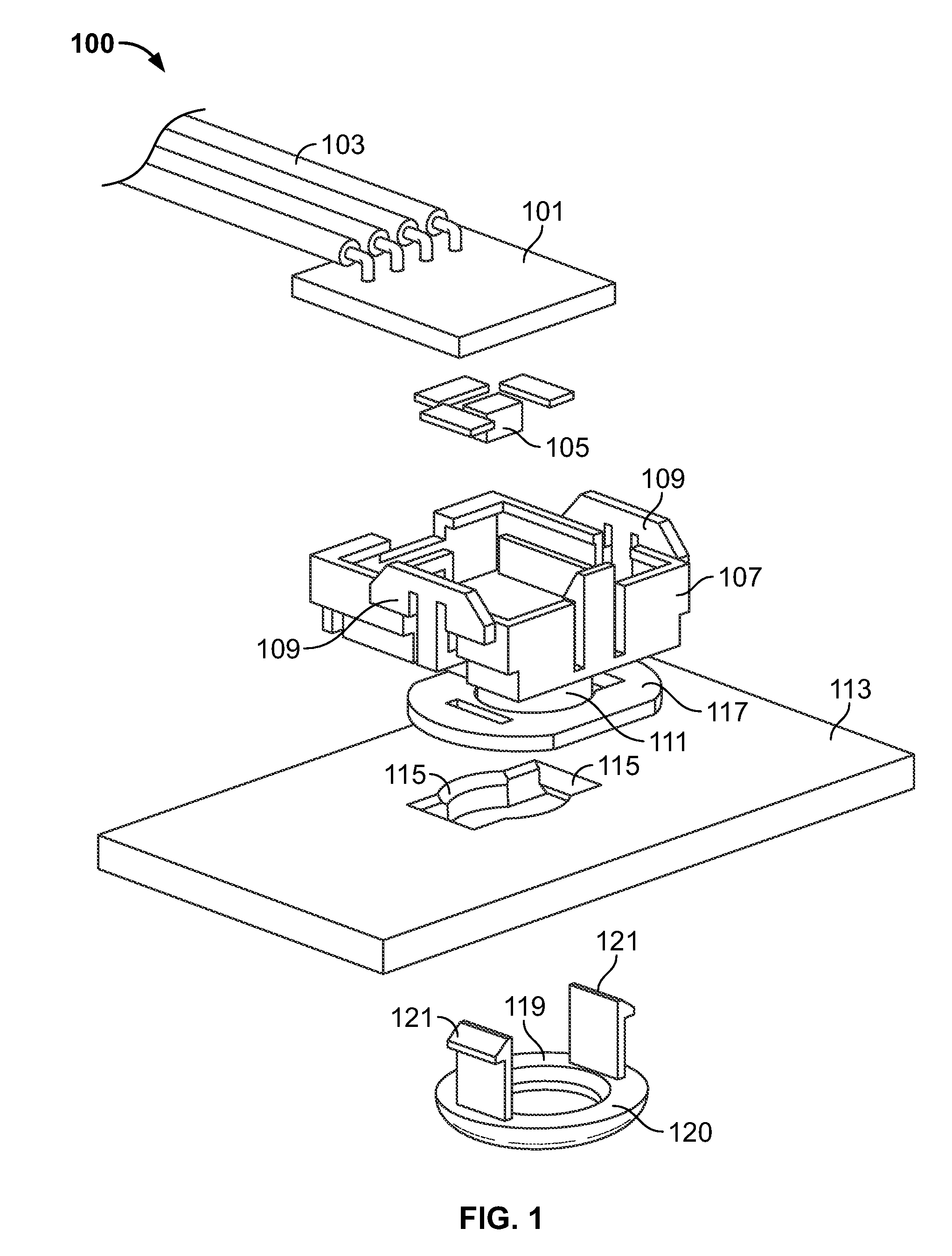
[0020]FIG. 1 shows an exploded view of a panel mounted light emitting element assembly 100 according to an embodiment of the present disclosure. The assembly 100 includes a mounting board 101 having wires 103 in electrical communication therewith. Light emitting elements 105 may include any devices capable of providing illumination. Suitable light emitting elements 105 may include any light emitting elements 105 known for providing illumination, such as, but not limited to, light emitting diodes (LEDs), laser diodes, organic light emitting diodes (OLEDs), incandescent lights, fluorescent lights, polymer light emitting diodes, emissive phosphor lights and electroluminescent lights. Mounting board 101 may be any device, surface, structure or substrate capable of supporting, controlling and / or providing power to light emitting elements 105. Suitable structures for use as mounting board 101 includes, but is not limited to printed circuit boards (PCB). In addition, wires 103 may be any c...


PUM


Abstract

A light emitting element assembly for mounting to a panel. The assembly includes a housing configured to receive a light emitting element therein. In addition, the assembly includes a bezel having at least one latch arm extending from a surface of the bezel, wherein the bezel is configured to detachably engage a surface within the housing. The bezel is further configured to retain the assembly in a position relative to the panel. The assembly also includes a mounting structure having the light emitting element operably mounted therein.

Description

FIELD OF THE INVENTION[0001]The disclosure relates generally to light emitting assemblies and system, and more particularly, the disclosure relates to a panel mounted light emitting element, assembly and system.BACKGROUND OF THE INVENTION[0002]Recent technological advances in low voltage light sources, such as light emitting diodes (LEDs), now present low voltage light sources as suitable candidates as light sources. Low voltage light sources operate at a small fraction of the electrical power of conventionally used light sources and are an attractive option due to generally lower cost and higher efficiency than conventionally used light sources.[0003]A specific use of an LED based light may be a small pin light emitting element assembly for spot illumination. These pin spot lights may be panel mounted for directing the illumination. In some proposed applications, the entire pin spot light assembly must be sufficiently small to fit in restricted spaces. Additionally, the light emitt...

Claims


Application Information

Patent Timeline
Patent Type & Authority Patents(United States)
IPC IPC(8): H02B1/01
CPCB60Q3/0203F21V5/04F21V21/04F21Y2105/00F21Y2101/02F21Y2115/10B60Q3/51
Inventor GOTO, KAZUHIRO
Owner TYCO ELECTRONICS CANADA
Why Eureka
Try Eureka