Image processing method and image processing apparatus

a technology of image processing and image processing apparatus, which is applied in the field of image processing technique for implementing mixed reality, can solve the problems of high cost, difficult cost adoption, and expensive apparatus such as a large-scale measuring device, and achieve the effect of simple arrangemen

Inactive Publication Date: 2010-06-01
CANON KK
View PDF37 Cites 28 Cited by
  • Summary
  • Abstract
  • Description
  • Claims
  • Application Information

AI Technical Summary

Benefits of technology

[0010]The present invention has been made in consideration of the aforementioned conventional problems, and has as its principal object to provide an image processing method and apparatus, which can correctly express the depth ordering of real and virtual objects by a simple arrangement.
[0013]With such arrangement, according to the present invention, the depth ordering of real and virtual objects can be correctly and easily expressed.

Problems solved by technology

However, when the depth must be considered, e.g., when the user manipulates a virtual object by moving the stylus as a real object in his or her hand, a problem is posed.
However, in order to precisely measure the depth information of real space in real time, an expensive apparatus such as a large-scale measuring device, multi-view stereo camera system, and the like must be used.
For this reason, such method is often difficult to be adopted in terms of cost, thus calling improvements.
However, depth information obtained from two-view stereo camera images has low precision and resolution.
Hence, such method is difficult to be adopted in an application that attaches importance on accurate expression of the depth ordering.
The manual registration process of the color information requires knowledge and skills, and is not a process that everyone can easily make.

Method used


Image

  • Image processing method and image processing apparatus
  • Image processing method and image processing apparatus
  • Image processing method and image processing apparatus

Examples


first embodiment

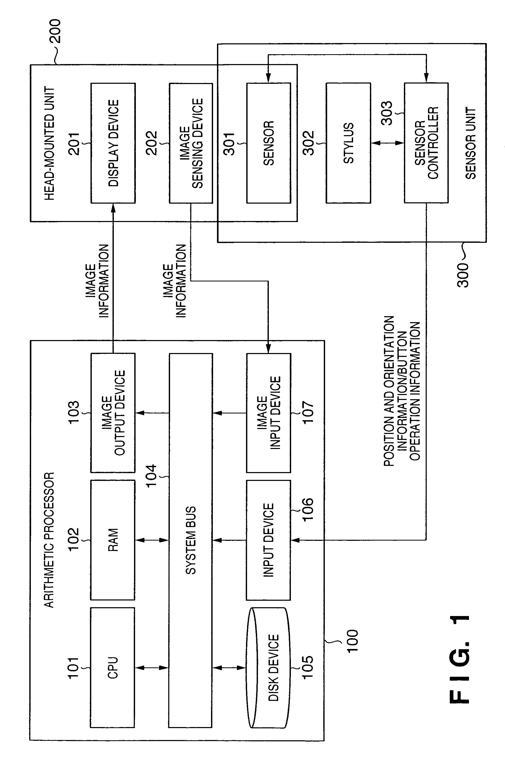
[0031]FIG. 1 is a block diagram showing an example of the arrangement of an MR system using an image processing apparatus according to the first embodiment of the present invention.

[0032]Referring to FIG. 1, the MR system comprises an arithmetic processor 100 as an image processing apparatus according to this embodiment, a head-mounted unit 200 which is mounted on the head of the user, and a sensor unit 300 used to detect the positions and orientations of a stylus and user's viewpoint.

[0033]The arithmetic processor 100 includes, e.g., a computer, which comprises a CPU 101, RAM 102, image output device 103, system bus 104, disk device 105, input device 106, and image input device 107.

[0034]The CPU 101 controls respective units of the arithmetic processor 100 by executing an image processing program stored in, e.g., the disk device 105, thus implementing an image process to be described later. The CPU 101 is connected to the system bus 104, and can communicate with the RAM 102, image ...

second embodiment

[0073]An MR system using an image processing apparatus according to the second embodiment of the present invention will be described below. Since the MR system according to the second embodiment has the same system arrangement as that explained in the first embodiment using FIGS. 1 and 2, a description thereof will be omitted.

[0074]FIG. 4 is a flowchart for explaining the overall operation of the MR system according to this embodiment. Note that the program codes required to implement the processing to be described below are stored in a storage device such as the disk device 105, RAM 102, or the like, and are read out and executed by the CPU 101.

[0075]Steps S2000 to S2020 are the same as steps S1000 to S1020 in FIG. 3. In step S2000, a process for initializing the apparatus is executed. The initialization includes processes (e.g., to turn on respective devices which form the apparatus, launch a program, and so forth) to be executed first upon advancing the processing sequence of thi...

third embodiment

[0094]An MR system using an image processing apparatus according to the third embodiment of the present invention will be described below. Since the MR system according to the third embodiment has the same system arrangement as that explained in the first embodiment using FIGS. 1 and 2, a description thereof will be omitted.

[0095]FIG. 5 is a flowchart for explaining the overall operation of the MR system according to this embodiment. Note that the program codes required to implement the processing to be described below are stored in a storage device such as the disk device 105, RAM 102, or the like, and are read out and executed by the CPU 101.

[0096]Since steps S3000 to S3020 in FIG. 5 are the same as steps S1000 to S1020 in FIG. 3, a description thereof will be omitted.

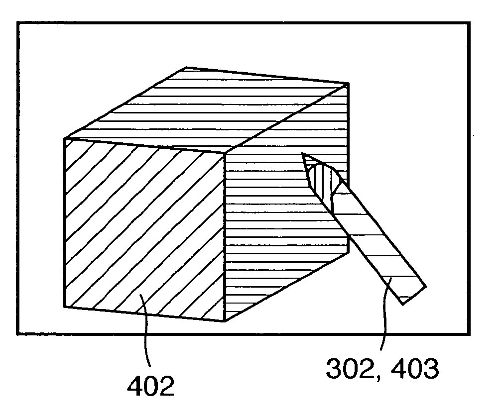
[0097]In step S3030, a collision checking process is executed on the basis of the positional relationship between the virtual model 402 (virtual object) and the stylus 302. However, as has been explained in the first...


PUM


Abstract

A virtual object and stylus model as images to be composited to a real space image are rendered by changing background transparencies according to a mutual positional relationship. When the virtual object image is composited to the real space image, the image of the stylus included in the real space image is observed while reflecting the positional relationship with the virtual object. In this way, in an MR image, the depth ordering between real and virtual objects can be correctly and easily expressed.

Description

CLAIM OF PRIORITY[0001]This application claims priority from Japanese Patent Application No. 2004-106244 filed on Mar. 31, 2004, which is hereby incorporated by reference herein.FIELD OF THE INVENTION[0002]The present invention relates to an image processing technique for implementing mixed reality and, more particularly, to an image processing technique which can correctly and easily express the depth ordering of a real object and virtual object.BACKGROUND OF THE INVENTION[0003]Systems that make use of a mixed reality (MR) technique which naturally composites the real and virtual spaces have been extensively proposed. A typical MR system has the following arrangement. That is, an MR image is generated by aligning and compositing a virtual space image rendered by computer graphics (CG) to a real space image sensed by an image sensing device such as a camera or the like. The MR image is displayed on a display device such as a head-mounted display (HMD) that the user (observer / experie...

Claims


Application Information

Patent Timeline
Patent Type & Authority Patents(United States)
IPC IPC(8): G09G5/00G02B1/00G06F3/00G06F3/01G06F3/033G06T3/00G06T5/50G06T15/00G06T19/00H04N5/272
CPCG06F3/012G06F3/0338G06F3/03542G06T15/405G06T15/503G06T19/006G06F3/03545G06T2210/62
Inventor SUZUKI, MASAHIROMORITA, KENJI
Owner CANON KK
Why Eureka
Try Eureka