Backlight unit and display device having the same

a backlight unit and display device technology, applied in the direction of lighting and heating equipment, instruments, machines/engines, etc., can solve the problems of poor color reproducibility, low power consumption of lamps, general insufficient brightness, etc., and achieve the effect of superior color reproducibility and low power consumption

Inactive Publication Date: 2010-06-01
SAMSUNG ELECTRONICS CO LTD
View PDF18 Cites 70 Cited by
  • Summary
  • Abstract
  • Description
  • Claims
  • Application Information

AI Technical Summary

Benefits of technology

[0011]Accordingly, it is an aspect of embodiments of the present invention to substantially solve the above and other problems, and to provide a backlight unit having superior color reproducibility and low power consumption.
[0012]Accordingly, it is another aspect of embodiments of the present invention to provide a display device comprising a backlight unit having superior color reproducibility and low power consumption.

Problems solved by technology

The direct type backlight unit provides a high level of brightness by using a plurality of light sources, as compared with the edge type backlight unit, but the brightness is generally not sufficiently uniform.
The lamp has low power consumption, but has poor color reproducibility.
Alternatively, the LED has good color reproducibility, long life spans, and fast instant lighting, but has high power consumption and greater heat generation.

Method used


Image

  • Backlight unit and display device having the same
  • Backlight unit and display device having the same
  • Backlight unit and display device having the same

Examples


first embodiment

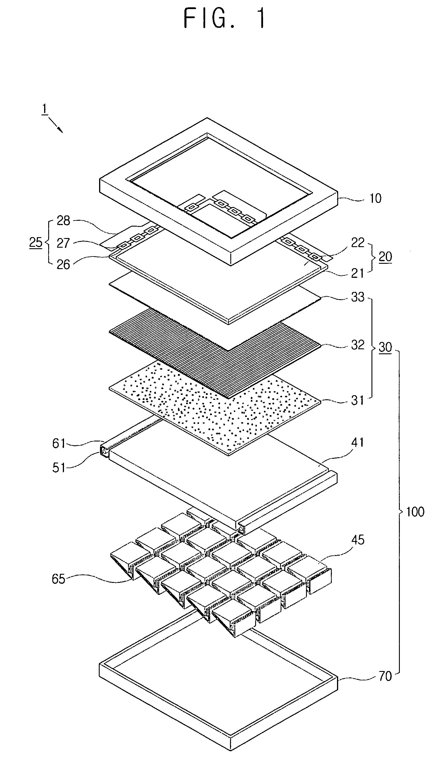
[0043]An exemplary liquid crystal display according to the present invention will now be described with reference to the FIGS. 1 and 2.

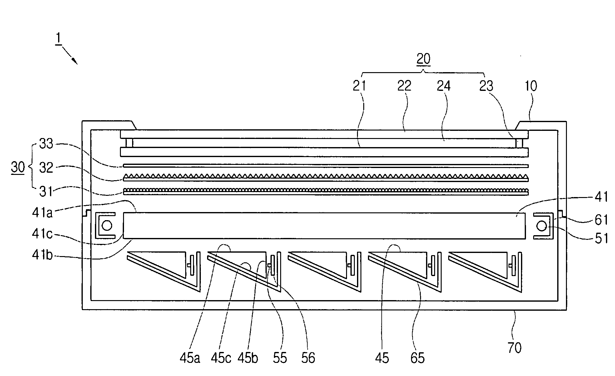
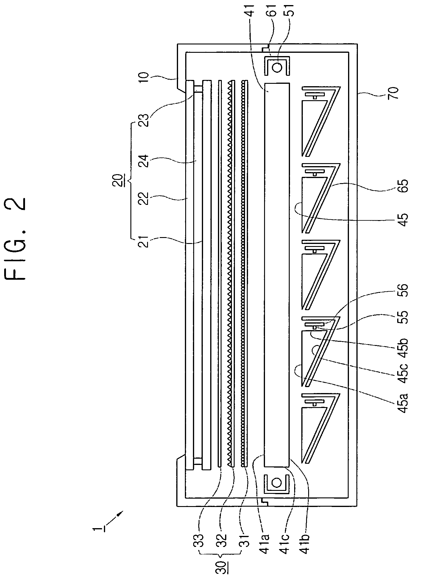
[0044]FIG. 1 is an exploded perspective view of a liquid crystal display according to a first embodiment of the present invention, and FIG. 2 is a sectional view of the liquid crystal display according to the first embodiment of the present invention.

[0045]A liquid crystal display (LCD) 1 comprises an LCD panel 20 and a backlight unit 100 providing light for the LCD panel 20. The backlight unit 100 comprises a light regulating part 30, a first light guide plate 41, a second light guide plate 45, a lamp 51, a light emitting diode (LED) 55, and a reflecting plate 65.

[0046]The LCD panel 20, the light regulating part 30, the first light guide plate 41, the second light guide plate 45, the lamp 51, the LED 55, and the reflecting plate 65 are accommodated between an upper chassis 10 and a lower chassis 70.

[0047]The LCD panel 20 comprises a TFT substrate 21...

second embodiment

[0064] shown in FIG. 3, the second light guide plate 45 is disposed above the first light guide plate 41.

[0065]The first light guide plate 41 having a flat plate shape, comprises the light exiting surface 41a facing the second light guide plate 45, a reflecting surface 41d provided on the opposite side of the light exiting surface 41a, and a pair of light incident surfaces 41e facing the lamps 51.

[0066]The second light guide plate 45 having a wedge shape comprises the light exiting surface 45a exiting light therefrom, a first incident surface 45d facing the LED 55, and a second incident surface 45e facing the first light guide plate 41.

[0067]The light generated from the lamp 51 exits the light exiting surface 41a of the first light guide plate 41 and enters the second incident surface 45e of the second light guide plate 45 and is then mixed with light generated from the LED 55. The mixed light exits the light exiting surface 45e of the second light guide plate 45.

[0068]A reflecting ...

third embodiment

[0069]According to the present invention as shown in FIG. 4, a first light guide plate 42 has a wedge shape and the lamp 51 is disposed on one side of the first light guide plate 42. The second light guide plate 45 is disposed above the first light guide plate 42.


PUM

PropertyMeasurementUnit
distanceaaaaaaaaaa
shapeaaaaaaaaaa
color reproducibilityaaaaaaaaaa

Abstract

A backlight unit and method of use are provided having a first light guide plate, a linear light source disposed along at least one side edge of the first light guide plate, a plurality of second light guide plates facing the first light guide plate, and a point light source disposed along at least one side edge of each second light guide plate. Accordingly, the present invention can provide a backlight unit using both a point light source and a linear light source at substantially the same time, and having superior color reproducibility and low power consumption.

Description

CROSS-REFERENCE TO RELATED APPLICATIONS[0001]This application claims the benefit under 35 U.S.C. §119(a) of Korean Patent Application No. 10-2005-0084074, filed in the Korean Intellectual Property Office on Sep. 9, 2005, the entire disclosure of which is hereby incorporated by reference.BACKGROUND OF THE INVENTION[0002]1. Field of the Invention[0003]The present invention relates to a backlight unit and a display device having the same. More particularly, the present invention relates to a backlight unit and a display device having the same which is capable of providing superior color reproducibility and low power consumption by using a point light source and a linear light source at substantially the same time.[0004]2. Description of the Related Art[0005]Recently, a flat panel display apparatus, such as a liquid crystal display (LCD), a plasma display panel (PDP), and an organic light emitting diode (OLED), has been developed to substitute for a conventional display such as a cathod...

Claims


Application Information

Patent Timeline
Patent Type & Authority Patents(United States)
IPC IPC(8): G02F1/1335F21V7/04G01D11/28
CPCG02F1/133609G02B6/0078G02F1/133603G02B6/0076G02B6/0046G02B6/0055G02F1/1335
Inventor KIM, SU-GUNCHO, TAE-HEESEONG, KI-BUMLEE, JUN-YOUNGKIM, JUNG-HYEON
Owner SAMSUNG ELECTRONICS CO LTD
Why Eureka
Try Eureka