System and method for correcting attitude estimation

a technology of attitude estimation and system, applied in the field of attitude correction of instruments, can solve the problems of insufficient accuracy of the attitude data provided by the iru, latency in data transfer of the rate data from the spacecraft, and additional errors caused by the spacecraft, so as to reduce the error of orientation attitud

Active Publication Date: 2010-06-01
HARRIS CORP
View PDF5 Cites 17 Cited by
  • Summary
  • Abstract
  • Description
  • Claims
  • Application Information

AI Technical Summary

Benefits of technology

[0021]To meet this and other needs, and in view of its purposes, the present invention provides a compensator for reducing attitude errors in orientation of a line-of-sight controlled by an instrument. The compensator includes a transfer function module configured to operate on an input signal and, in response, provide a compensated output signal. The transfer function module is coupled to an angular rate sensor for receiving, as the input signal, angular rates from the angular rate sensor, and the transfer function module is coupled to the instrument for providing compensated angular rates as the compensated output signal.

Problems solved by technology

The attitude data provided by the IRU, unfortunately, may not be accurate enough because, for example, the spacecraft's star trackers may not be sufficiently accurate.
During integration of the IRU rate data to derive attitude data, unfortunately, errors are caused by the latency in data transfer of the rate data from the spacecraft to the instrument.
Additional errors may be caused by the spacecraft's IRU dynamics.

Method used


Image

  • System and method for correcting attitude estimation
  • System and method for correcting attitude estimation
  • System and method for correcting attitude estimation

Examples


first embodiment

[0058]Referring next to FIG. 3, there is shown rate sensor dynamics and latency compensator 25. As shown, compensator 25 includes a constant gain, or fixed gain transfer function, generally designated as 31. In this embodiment, the compensation output, θcomp), is related to the compensation input, r, by the compensation gain constant, Kcomp:

θcomp=Kcompr

second embodiment

[0059]Referring next to FIG. 4, there is shown rate sensor dynamics and latency compensator 25. As shown, compensator 25 includes a transfer function that varies as a function of frequency, generally designated as 41. In this embodiment, the compensation output, θcomp, is related to the compensation input, r, by a general difference equation. A representative second-order difference equation is:

θcomp(n)=−a1θcomp(n−1)−a2θcomp(n−2)+b0r(n)+b1r(n−1)+b2 r(n−2)

where the constants a1, a2, b0, b1, and b2 are chosen to match the desired transfer function. The desired transfer function may be of any order.

[0060]It will be understood that compensators 31 and 41 may be of an analog implementation or a digital implementation.

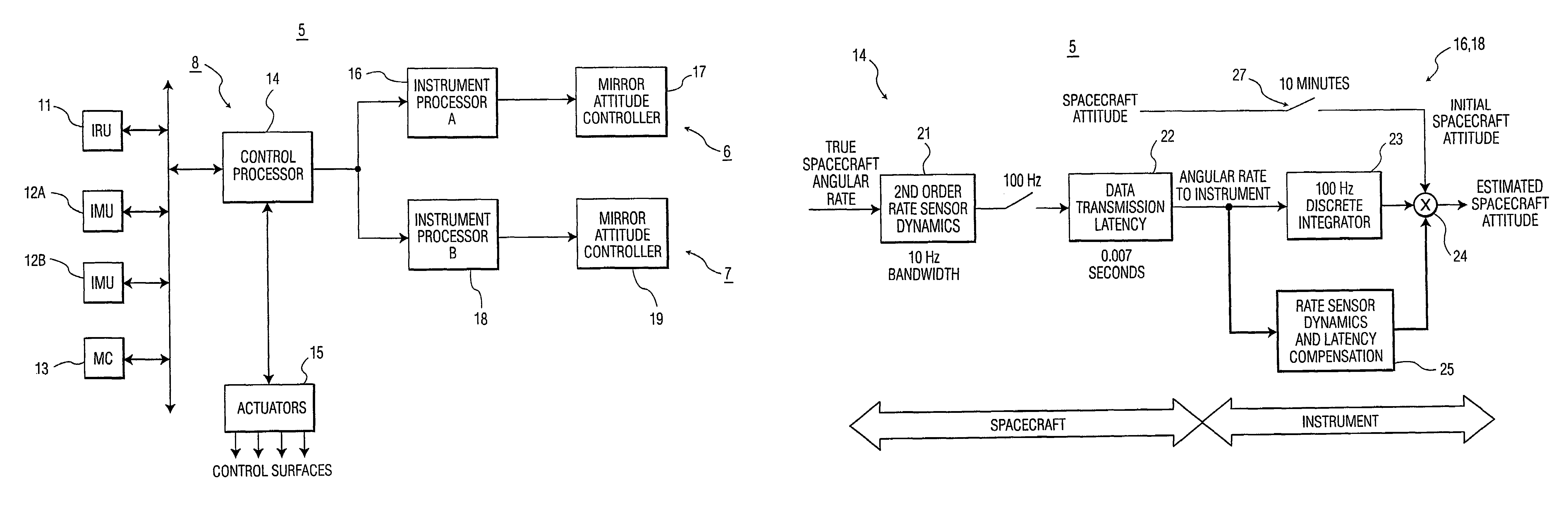
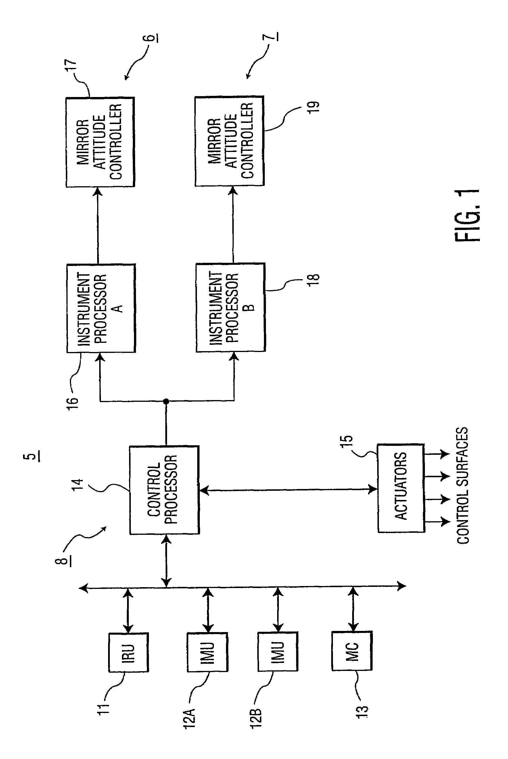
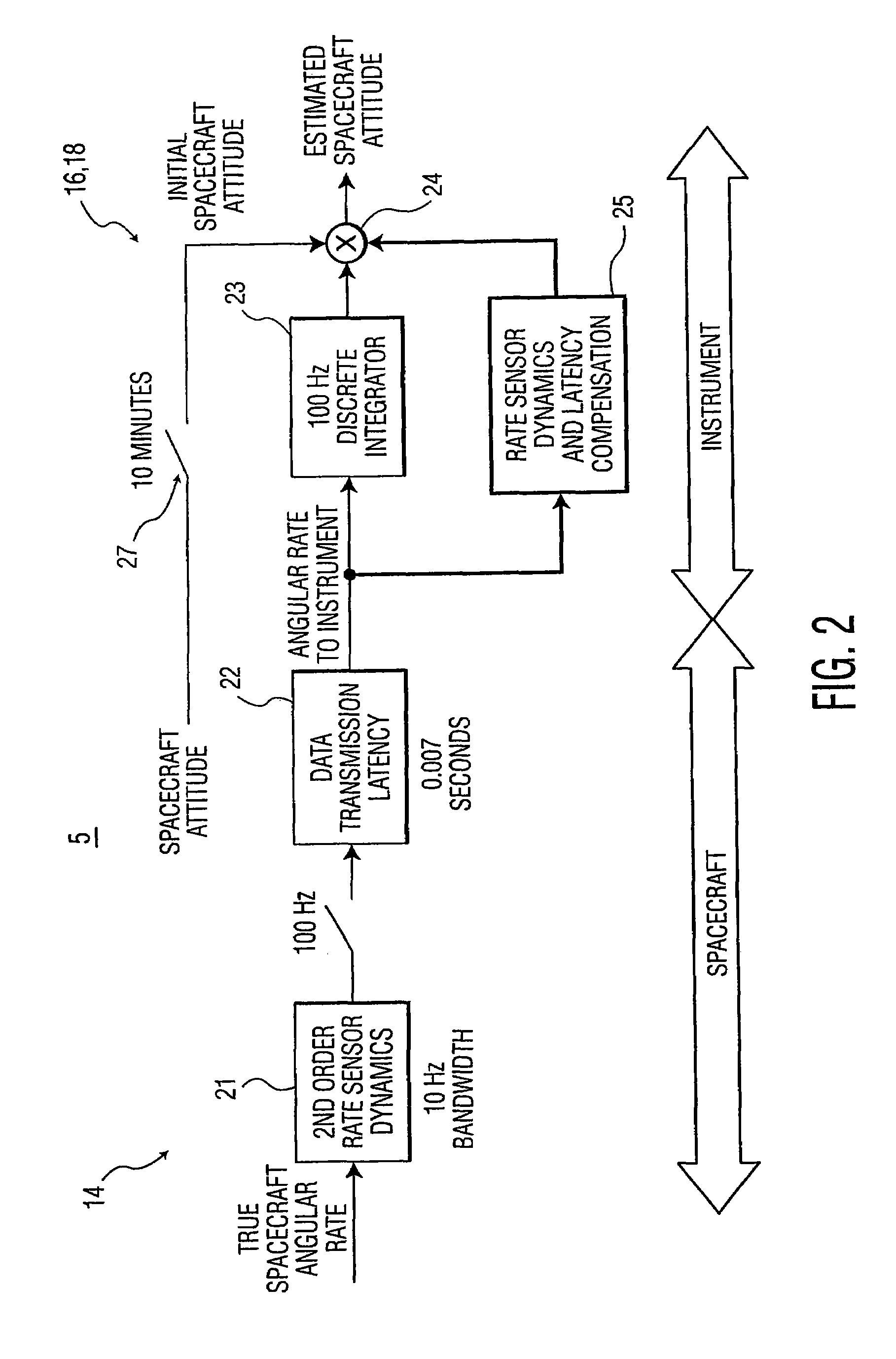
[0061]It will be understood that the present invention may be used with any instrument, or device disposed in a vehicle, or spacecraft, where the instrument, or device requires short term attitude information from a remote device having a rate sensor disposed in the same veh...


PUM


Abstract

A system includes an angular rate sensor disposed in a vehicle for providing angular rates of the vehicle, and an instrument disposed in the vehicle for providing line-of-sight control with respect to a line-of-sight reference. The instrument includes an integrator which is configured to integrate the angular rates of the vehicle to form non-compensated attitudes. Also included is a compensator coupled across the integrator, in a feed-forward loop, for receiving the angular rates of the vehicle and outputting compensated angular rates of the vehicle. A summer combines the non-compensated attitudes and the compensated angular rates of the to vehicle to form estimated vehicle attitudes for controlling the instrument with respect to the line-of-sight reference. The compensator is configured to provide error compensation to the instrument free-of any feedback loop that uses an error signal. The compensator may include a transfer function providing a fixed gain to the received angular rates of the vehicle. The compensator may, alternatively, include a is transfer function providing a variable gain as a function of frequency to operate on the received angular rates of the vehicle.

Description

STATEMENT REGARDING FEDERALLY SPONSORED RESEARCH[0001]The invention described herein was made in the performance of work under NASA Contract No. NNG04HZ07C and is subject to the provisions of Section 305 of the National Aeronautics and Space Act of 1958 (42 U.S.C. 2457).TECHNICAL FIELD[0002]The present invention relates, in general, to attitude correction of an instrument controlling its own line-of-sight. More specifically, the present invention relates to a lead compensator to correct for rate sensor dynamics and data transfer latency between a sensor disposed in a vehicle and an instrument controlling its own line-of-sight.BACKGROUND OF THE INVENTION[0003]A geostationary satellite maintains its orbit and attitude such that its z-axis points to a sub-satellite point or to nadir. The spacecraft control system maintains the satellite 3-axis attitude (roll, pitch, and yaw) near 0° for all three axes, typically with less than 0.1° error. The spacecraft angular rates are usually small ...

Claims


Application Information

Patent Timeline
Patent Type & Authority Patents(United States)
IPC IPC(8): G05D1/08
CPCG05D1/0883B64G1/36B64G1/244
Inventor JOSSELSON, ROBERT H.
Owner HARRIS CORP
Why Eureka
Try Eureka