Test postcondition items for automated analysis and test generation

a postcondition item and automated analysis technology, applied in the field of automated analysis postcondition item test generation, can solve the problems of time-consuming and resource-intensive, incomplete simulation, and inability to run comprehensive or multiple verification scenarios in a verification tool

Active Publication Date: 2010-06-01
THE MATHWORKS INC
View PDF14 Cites 13 Cited by
  • Summary
  • Abstract
  • Description
  • Claims
  • Application Information

AI Technical Summary

Benefits of technology

[0010]The postcondition element may be used to ensure that the verification covers the more meaningful, interesting, or practical scenarios of the behavior of the system under design and that the design can achieve performance or behavior goals. The postcondition element assists a designer in performing guided design exploration of areas of interest via formal analysis. In summary, the postcondition element of the present invention provides a mechanism for the designer in the modeling environment to provide instructions or directives to a verification or testing tool to verify or test the design by providing objectives or goals for the verification as opposed to constraints or limitations (i.e. preconditions).

Problems solved by technology

Although simulation may be used to functionally verify some behavior of the design, simulation may not be exhaustive such that it covers all desired or unwanted circumstances and occurrences of design behavior.
Running comprehensive or multiple verification scenarios in a verification tool may be time consuming and resource intensive.
The techniques and methods used by the verification tool may exercise behavior or functionality that is not of concern to the model-based designer or that is not practical or realistic in the intended application of the implementation of the model-based design.
Therefore, it may be time consuming, resource intensive or inconvenient to obtain or review the results of the portion of the verification that is of interest to the designer or realistic for the design.
Generating verification scenarios in a verification tool may consume significant time and resources.
Thus, it may be challenging to relate the verification scenario configuration and verification results to the model-based design represented by the graphical model.
One disadvantage of such an implementation is that in order to test if a design behaves or functions as desired, the designer must provide the proper inputs or preconditions that are necessary to cause the design to provide a desired result or behavior.

Method used


Image

  • Test postcondition items for automated analysis and test generation
  • Test postcondition items for automated analysis and test generation
  • Test postcondition items for automated analysis and test generation

Examples


Embodiment Construction

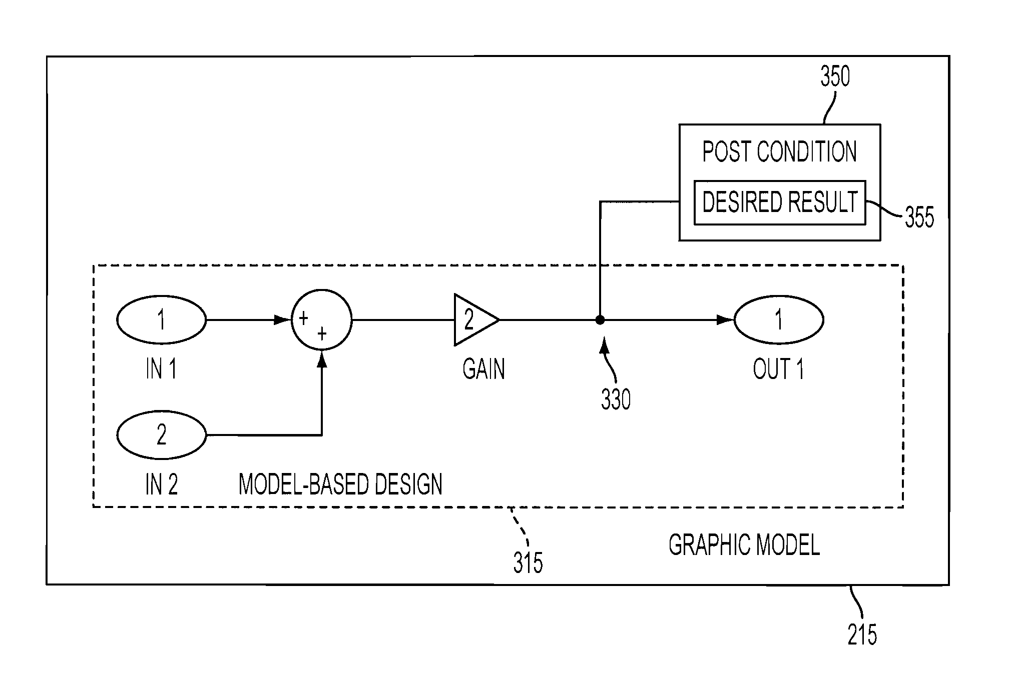
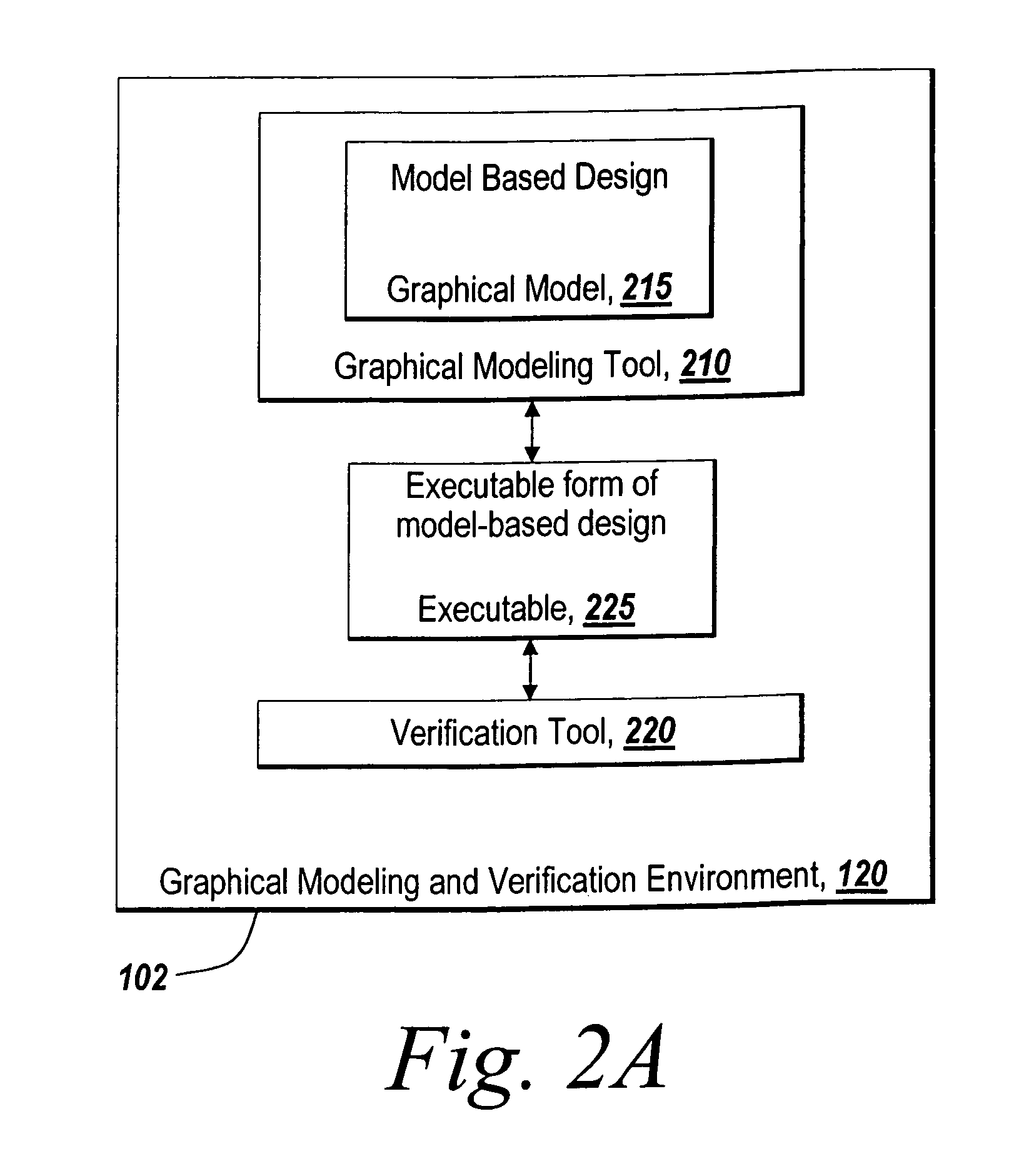
[0038]The illustrative embodiment of the present invention provides systems and methods for using an element in a graphical model to represent and identify a postcondition for use by a verification tool in verifying an executable form of the design represented by the graphical model. The postcondition element provides a specification of a desired result or objective to be achieved or tested for by the verification tool in the verification of the design without affecting the behavior of the design. The postcondition element may not be incorporated directly into the model-based design represented by the graphical model but may be associated with graphical model elements as a design specification for verification. Additionally, the postcondition element may be configurable to provide different logics for the desired result and can be set to be active or inactive. As the graphical model may reference or otherwise have a hierarchy of graphical models, there may be multiple postcondition ...


PUM


Abstract

The present invention provides methods and systems for using a element in a graphical model to represent and identify a postcondition for use by a verification tool in verifying an executable form of the design represented by the graphical model. The postcondition element comprises desired result for verification without affecting the behavior of the design. The desired result is to be achieved or tested for in verifying the design. As such, the postcondition element of the present invention provides a mechanism and formalism in a model-based design approach that is used to direct automatically generated tests or verification of the design represented by the graphical model.

Description

RELATED APPLICATIONS[0001]This application is related to application Ser. No. 11 / 096,528 filed on Mar. 31, 2005, entitled “Test Precondition Items for Automated Analysis and Test Generation.”TECHNICAL FIELD[0002]The present invention generally relates to associating a postcondition element with a model-based design represented by a graphical model for use by a verification tool in verifying the model-based design.BACKGROUND INFORMATION[0003]Graphical modeling environments are products that enable a user to construct and analyze a model of a process or system. Examples of graphical modeling formalisms for which graphical modeling environments exist include time-based block diagrams, such as those supported by Simulink® from The MathWorks Inc., discrete event diagrams and reactive state machine diagrams, such as those supported by Stateflow® also available from The MathWorks, Inc., entity flow diagrams such as those supported by SimEvents, available from The MathWorks, Inc., data-flow...

Claims


Application Information

Patent Timeline
Patent Type & Authority Patents(United States)
IPC IPC(8): G06F9/455
CPCG06F8/34
Inventor ALDRICH, WILLIAM J.
Owner THE MATHWORKS INC
Why Eureka
Try Eureka