Flow control mechanism

a control mechanism and flow control technology, applied in the field of transfer of data, can solve the problems of system underutilization, excessive system capacity, and maximum rate at which data is provided for transmission, and achieve the effect of increasing the network latency tim

Active Publication Date: 2010-06-01
EMC IP HLDG CO LLC
View PDF14 Cites 9 Cited by
  • Summary
  • Abstract
  • Description
  • Claims
  • Application Information

AI Technical Summary

Benefits of technology

[0010]According to the present invention, transferring data elements from a source to a destination includes providing a transmission queue at the source, wherein data elements in the transmission queue are transferred from the source to the destination, determining an optimal length for the transmission queue, where the optimal queue length is inversely proportional data latency time at the destination, and, if the optimal length is greater than an instantaneous length of the transmission queue, adding data elements to the transmission queue. Adding data elements may include adding a number of elements corresponding to a difference between the optimal length and the instantaneous length of the transmission queue. Determining optimal length may include dividing a constant by the data latency time at the destination. Transferring data elements may also include providing a network between the source and the destination. Transferring data elements may also include setting the constant according to network latency time and network bandwidth. Setting the constant may include increasing the constant as the network bandwidth increases. Setting the constant may include increasing the constant as the network latency time increases. Determining optimal length may include dividing a network variable by the data latency time at the destination, where the network variable varies according to network latency time and network bandwidth. The network variable may increase as the network bandwidth increases. The network variable may increase as the network latency time increases.
[0011]According further to the present invention, computer software that transfers data elements from a source to a destination includes executable code that provides a transmission queue at the source, where data elements in the transmission queue are transferred from the source to the destination, executable code that determines an optimal length for the transmission queue, wherein the optimal queue length is inversely proportional data latency time at the destination, and executable code that adds data elements to the transmission queue if the optimal length is greater than an instantaneous length of the transmission queue. Executable code that adds data elements may include executable code that adds a number of elements corresponding to a difference between the optimal length and the instantaneous length of the transmission queue. Executable code that determines optimal length may include executable code that divides a constant by the data latency time at the destination. The software may include executable code that provides a network between the source and the destination. The constant may be set according to network latency time and network bandwidth. The constant may be increased as the network bandwidth increases. The constant may be increased as the network latency time increases. Executable code that determines optimal length may include executable code that divides a network variable by the data latency time at the destination, where the network variable varies according to network latency time and network bandwidth. The network variable may increase as the network bandwidth increases. The network variable may increase as the network latency time increases.

Problems solved by technology

One difficulty with RDF (and many systems that make use of data communication) is that they can exhibit “bursts” of data so that the maximum rate at which data is provided for transmission exceeds the capacity of the system.
However, this solution could result in an over-design of the system and, in instances where extra communication bandwidth costs money, could result in extra unnecessary cost.
However, in situations where there is significant communication latency, it is necessary for the secondary storage device to send a signal to stop the flow long before the queue of the secondary storage device is close to full.
Thus, in many instances, XON / XOFF flow control will cause the system to be underutilized.
However, one drawback to this is that it assumes that the ability of the secondary storage device to process received data is fixed and it assumes that the bandwidth of the communication link is also fixed.
In instances where this is not the case, Windowing may not be appropriate.

Method used


Image

  • Flow control mechanism
  • Flow control mechanism
  • Flow control mechanism

Examples


Embodiment Construction

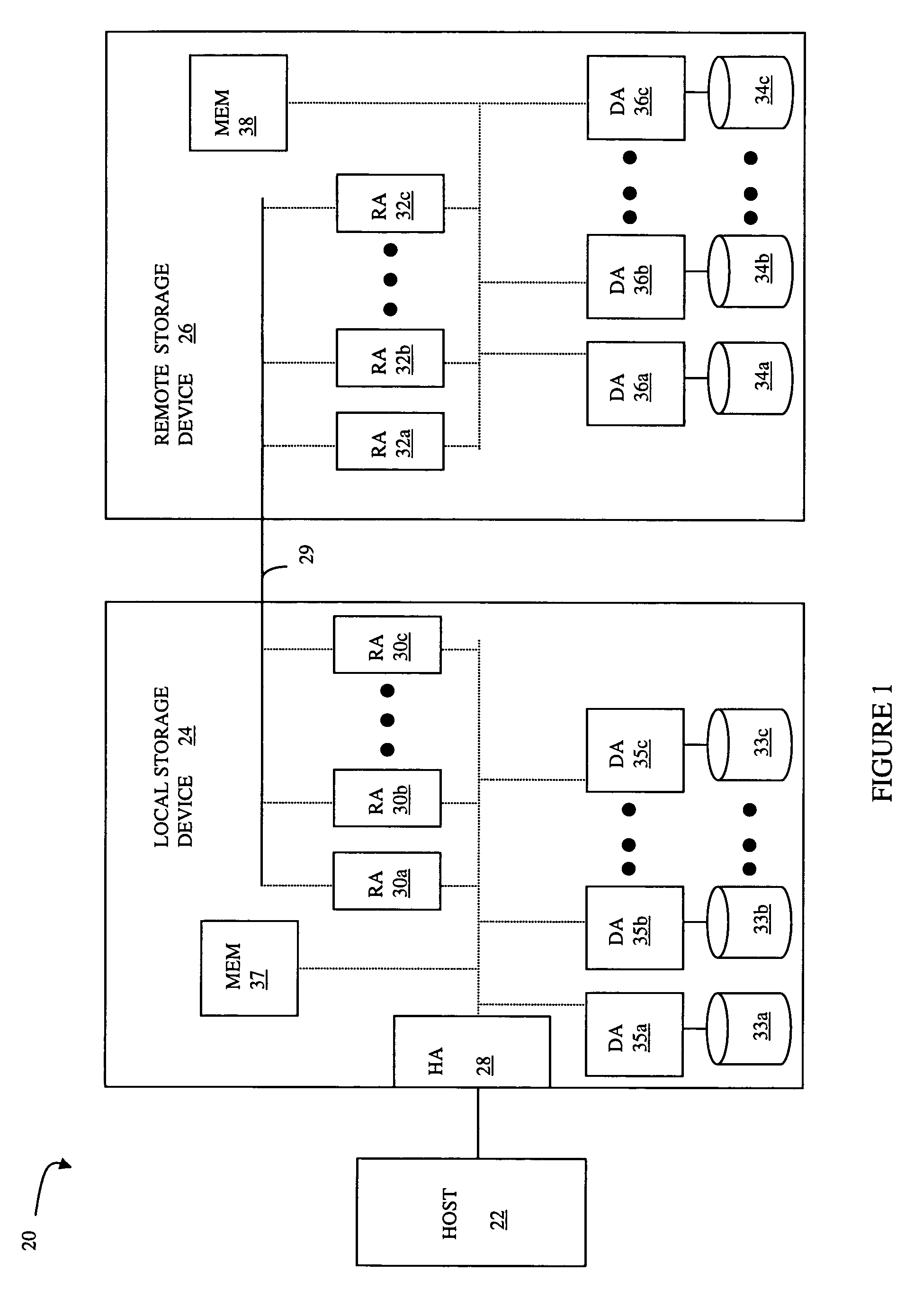
[0041]Referring to FIG. 1, a diagram 20 shows a relationship between a host 22, a local storage device 24 and a remote storage device 26. The host 22 reads and writes data from and to the local storage device 24 via a host adapter (HA) 28, which facilitates the interface between the host 22 and the local storage device 24. Although the diagram 20 only shows one host 22 and one HA 28, it will be appreciated by one of ordinary skill in the art that multiple HA's may be used and that one or more HA's may have one or more hosts coupled thereto.

[0042]Data from the local storage device 24 is copied to the remote storage device 26 via an RDF link 29 to cause the data on the remote storage device 26 to be identical to the data on the local storage device 24. Although only the one link 29 is shown, it is possible to have additional links between the storage devices 24, 26 and to have links between one or both of the storage devices 24, 26 and other storage devices (not shown). In addition, t...


PUM


Abstract

Transferring data elements from a source to a destination includes providing a transmission queue at the source, where data elements in the transmission queue are transferred from the source to the destination, determining an optimal length for the transmission queue, where the optimal queue length is inversely proportional data latency time at the destination, and, if the optimal length is greater than an instantaneous length of the transmission queue, adding data elements to the transmission queue. Adding data elements may include adding a number of elements corresponding to a difference between the optimal length and the instantaneous length of the transmission queue. Determining optimal length may include dividing a constant by the data latency time at the destination. Transferring data elements may also include providing a network between the source and the destination.

Description

BACKGROUND OF THE INVENTION[0001]1. Technical Field[0002]This application relates to computer storage devices, and more particularly to the field of transferring data between storage devices.[0003]2. Description of Related Art[0004]Host processor systems may store and retrieve data using a storage device containing a plurality of host interface units (host adapters), disk drives, and disk interface units (disk adapters). Such storage devices are provided, for example, by EMC Corporation of Hopkinton, Mass. and disclosed in U.S. Pat. No. 5,206,939 to Yanai et al., U.S. Pat. No. 5,778,394 to Galtzur et al., U.S. Pat. No. 5,845,147 to Vishlitzky et al., and U.S. Pat. No. 5,857,208 to Ofek. The host systems access the storage device through a plurality of channels provided therewith. Host systems provide data and access control information through the channels to the storage device and the storage device provides data to the host systems also through the channels. The host systems do no...

Claims


Application Information

Patent Timeline
Patent Type & Authority Patents(United States)
IPC IPC(8): G06F3/00G06F15/16
CPCH04L47/25H04L49/90H04L47/28
Inventor VEPRINSKY, ALEXANDRPANIDIS, ANESTISSHETTY, RAMPRASADGARELIK, ILYA E.HALSTEAD, MARK J.KORNFELD, SERGEY
Owner EMC IP HLDG CO LLC
Why Eureka
Try Eureka