
Head support and stabilization system

a head support and stabilization system technology, applied in the field of surgical equipment, can solve the problems of complex mounting of both devices from the same crossbar member, inflexible and inconvenient, and present special problems, and achieve the effects of reducing stress and strain on the patient's muscular and skeletal system, reducing the stress and strain on the patient's body, and being flexibl

Active Publication Date: 2010-06-08
INTEGRA LIFESCI
View PDF46 Cites 117 Cited by
  • Summary
  • Abstract
  • Description
  • Claims
  • Application Information

AI Technical Summary

Benefits of technology

[0006]The present invention provides a head support and fixation system that is highly flexible and can be used with a wide range of neuro-navigational and surgical procedures. The head support and fixation system of the present invention provides separate and independent support and stabilization devices, thereby providing greater flexibility and convenience to the user. The head support and fixation system of the present invention can be located close to an end of a patient support table, which permits a more complete support for smaller patients and minimizes stress and strain on the patient's muscular and skeletal systems. The head support and fixation system of the present invention is compact and does not require use of a base unit for supporting a skull clamp and therefore, provides more convenient and open access to smaller patients.

Problems solved by technology

In those situations where both subjacent support and lateral stabilization are required, having to mount both devices from the same crossbar member is complicated, inflexible and inconvenient.
Children around two years old and younger also present special issues with respect to a head support system.
Such young children do not often have a bone structure that permits the use of known skull clamps, and therefore, other head support systems are required.

Method used


Image

  • Head support and stabilization system
  • Head support and stabilization system
  • Head support and stabilization system

Examples


Embodiment Construction

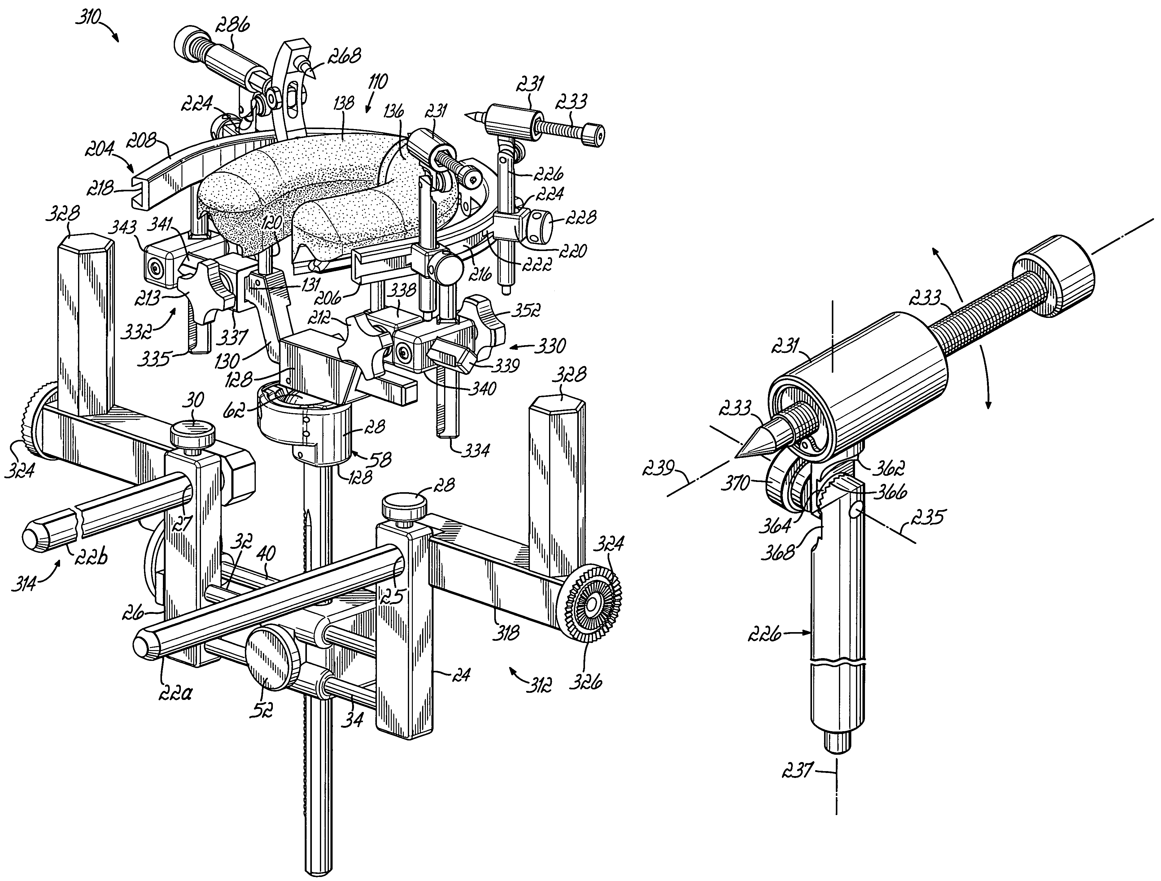
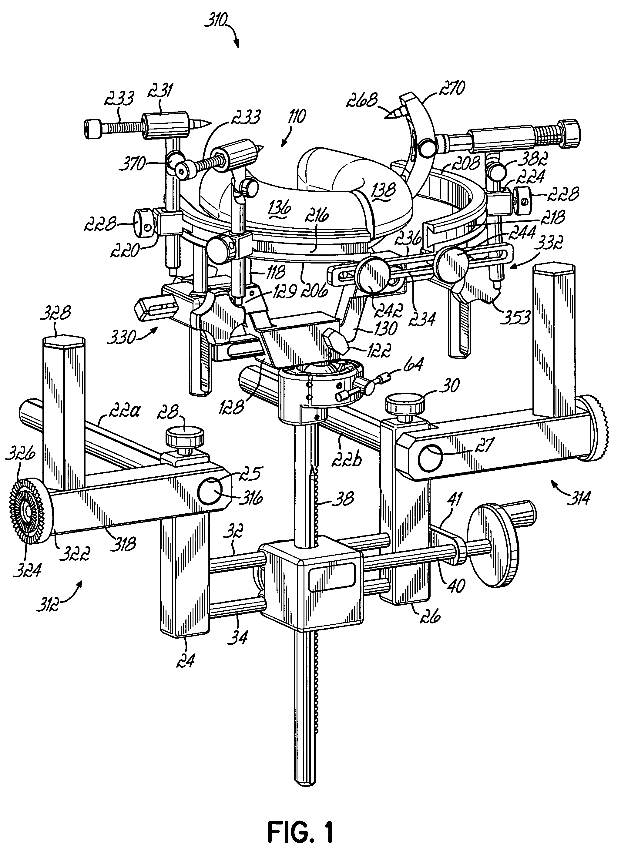
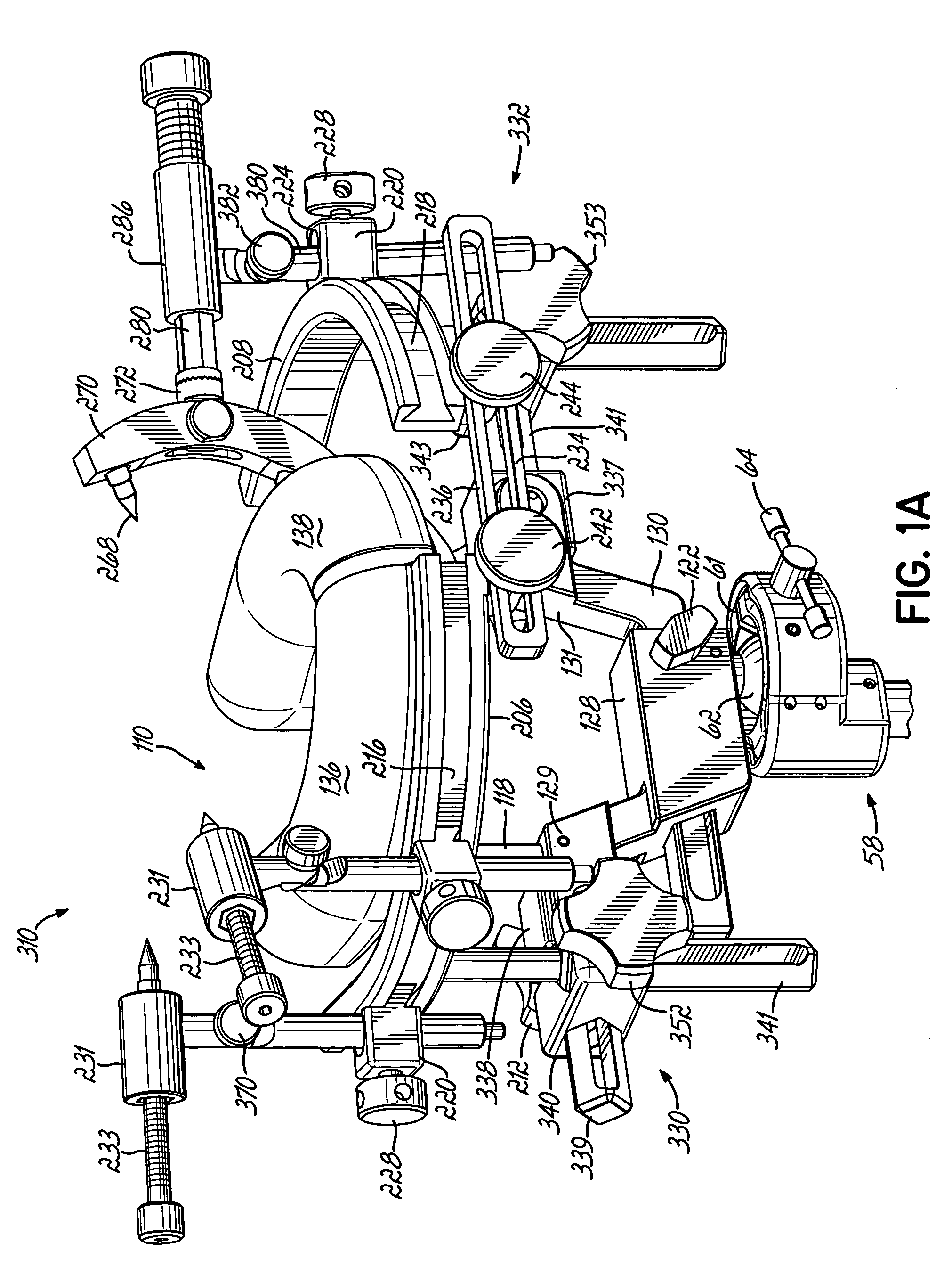
[0024]Referring to FIG. 1, in a first embodiment, a head support and stabilization system 310 is mounted on spaced-apart support shafts 22a, 22b that are connected in a known manner to an end of a patient support (not shown), for example, an operating table. The support shafts 22a, 22b extend substantially parallel with a length of the patient support. First and second support posts 24, 26 have respective bores 25, 27 (FIG. 2) that receive respective support shafts 22a, 22b. The support posts 24, 26 can be locked at a desired position by means of respective locking screws 28, 30. Upper and lower guide rods 32, 34 (FIG. 1) have first ends fixed in a lower portion of the first support post 24. Opposite ends of the guide rods 32, 34 are supported in a first, lower portion of the second support post 26. The guide rods 32, 34 extend through a gear box housing 36, and thus, the housing 36 is slidable longitudinally along the guide rods 32, 34 but cannot rotate with respect thereto. Also e...


PUM


Abstract

A head support system that has a fixation arc system that is adjustable both vertically and horizontally and is mounted to a patient support structure. The fixation arc system is positionable adjacent to, and provides lateral support for, the patient's head. A pin support is connected to, and extends from the fixation arc system. A pin is adjustably mounted to the pin support and contacts the patient's head to provide a lateral fixation thereof. The pin has a centerline that is rotatable about two axes of motion substantially perpendicular to the pin centerline.

Description

[0001]This application claims the benefit of U.S. Provisional Application No. 60 / 557,212, filed on Mar. 29, 2004 and U.S. Provisional Application No. 60 / 567,389, filed on Apr. 30, 2004, all of which are hereby expressly incorporated by reference hereinFIELD OF THE INVENTION[0002]This invention relates to surgical equipment and more particularly, to a head support system.BACKGROUND OF THE INVENTION[0003]During surgical procedures, one or more devices may be used to support a patient's head. For example, there may be a need to provide a static support for a patient's head; and typically, a static head support includes one or more pads that provide a static subjacent support of the patient's head in a prone or supine position. Such a static head support is mounted on a crossbar that extends transversely off the end of a patient support such as an operating table. Alternatively, a stabilization device, such as a skull clamp, is also used to support and stabilize a patient's head, and su...

Claims


Application Information

Patent Timeline
Patent Type & Authority Patents(United States)
IPC IPC(8): A61G13/12A61B19/00
CPCA61G13/121A61B19/203A61B90/14
Inventor SKLAR, FREDERICKDINKLER, II, CHARLES E.EASTON, KEVIN R.
Owner INTEGRA LIFESCI
Learn More