Indicator apparatus

Inactive Publication Date: 2010-06-08
CONTINENTAL AUTOMOTIVE GMBH
View PDF19 Cites 1 Cited by
  • Summary
  • Abstract
  • Description
  • Claims
  • Application Information

AI Technical Summary

Benefits of technology

[0014]Excellent readability is obtained if the ring pointer has a pointer lug which extends radially. In this way, the viewer is provided with the accustomed ergonomic impression of a classic pointer instrument. A maximum degree of stability and precision is obtained if the ring pointer is mounted at three points along the circumference in a radial direction in each case by use of a radial bearing. In order to facilitate assembly, one of the radial bearings can be embodied in a sprung manner so that it is elastically resilient in the radial direction.
[0015]The ring pointer expediently has a pointing element or a pointer lug and a base element which bears the pointing element and which is mounted in a decentralized fashion. Here, the base element is preferably annular. As a result of the off-center bearing, it is thus possible to dispense with a central pointer shaft or axle and nevertheless achieve the customary circular movement of the pointer. The central region which is enclosed by the movement path of the pointer can easily accommodate large displays such as, for example, LCD displays. At the same time, the drive unit of the pointer can advantage

Problems solved by technology

In the age of ever increasing information density in the cockpit of a motor vehicle, in particular manufacturers of combination instruments are faced with the difficult task of presenting a high density of information with, in some cases, safety related significance in a way which can be perceived satisfactorily.
In addition, this complex function must be provided with an attractive design, which frequently places strict limits on functionality and has a decisive influence on the requirements made of the overall structure.
Compared to conventional indicators with central indicator axes, the driving of the ring pointer, its bearing and it

Method used


Image

  • Indicator apparatus
  • Indicator apparatus

Examples


Embodiment Construction

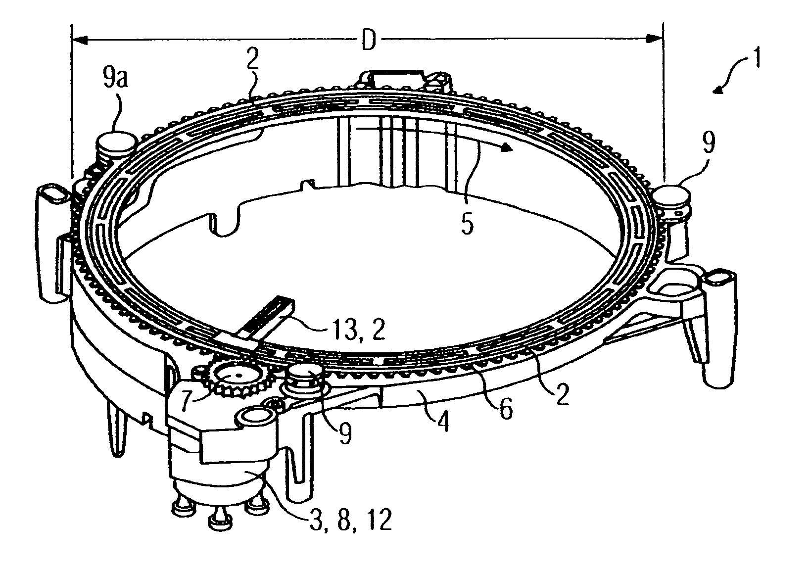
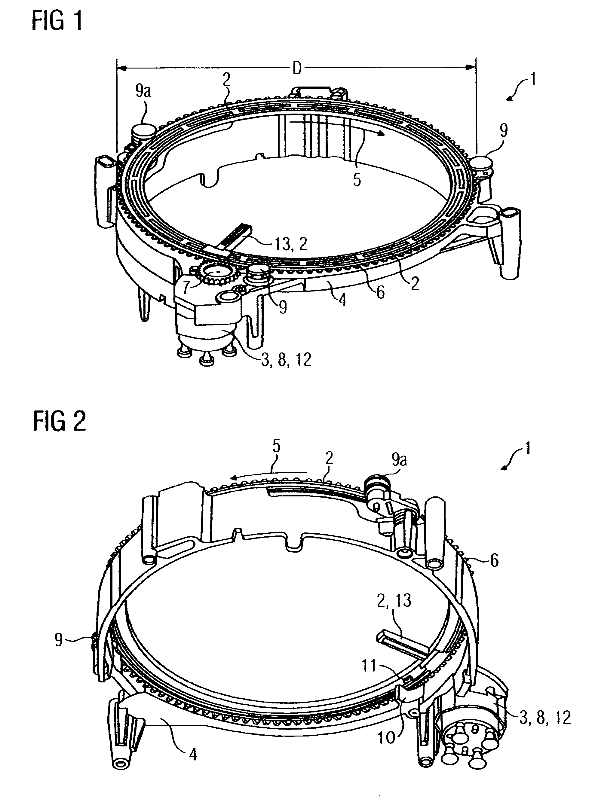
[0023]FIGS. 1 and 2 each illustrate an indicator apparatus 1 according to the invention, with an indication scale being omitted. The essential illustrated components are a ring pointer 2, a drive unit 3 and a carrier element 4. The ring pointer is provided on the outer diameter with a toothing 6 extending in the circumferential direction 5. The toothing 6 is connected to an output gear 7 of the drive unit 3 which has a stepping motor which ensures that the ring pointer 2 is driven in the circumferential direction or counter to the circumferential direction 5. The ring pointer 2 is mounted on the carrier element 4 by three radial bearings 9, 9a which each have a roller with a U-shaped end profile facing the carrier element, in which end profile the toothed outer circumference of the ring pointer is guided. The radial bearing 9a which is designated by 9a is embodied in a sprung manner, so that it is elastically resilient in the radially outer direction. In the direct vicinity of the d...


PUM


Abstract

The invention relates to an indicator apparatus (1) having a ring pointer (2), which is mounted such that it can move in the circumferential direction (5), and having a drive unit (3), which drives the ring pointer (2) in the circumferential direction (5), wherein the ring pointer (2) interacts with a stop (10) in a manner limited in terms of its circumferential movement. Particularly in the case of synchronization, radial disengagement often occurs in conventional ring pointer arrangements, and the aim of the invention is to prevent this. In order to solve the problem, the invention proposes arranging the stop (10) directly next to the drive unit (3). The critical advantage of this is that the tangential force on the ring pointer (2) from the drive unit generates an only small disengagement moment on the ring pointer (2).

Description

CROSS REFERENCE TO RELATED APPLICATIONS[0001]This is a U.S. national stage of application No. PCT / EP2006 / 066561, filed on Sep. 21, 2006. Priority is claimed on German application No. 10 2005 046 714.8, filed Sep. 29, 2005.BACKGROUND OF THE INVENTION[0002]The invention relates to an indicator apparatus having a ring pointer which is in the form of a ring or annular segment and is mounted so that it can move in the circumferentially. The indicator apparatus includes a drive unit which drives the ring pointer circumferentially, where the ring pointer has a stop face, and the indicator apparatus has a stop which interacts with the stop face so as to limit the circumferential movement of the ring pointer.[0003]In the age of ever increasing information density in the cockpit of a motor vehicle, in particular manufacturers of combination instruments are faced with the difficult task of presenting a high density of information with, in some cases, safety related significance in a way which ...

Claims


Application Information

Patent Timeline
IPC IPC(8): G01D11/16G01D13/22
CPCB60K37/02G01D13/22G01D11/16B60K2350/1064B60K2350/203B60K2370/154B60K2370/33B60K2370/698Y10S116/06
Inventor FORSTER, AXEL
Owner CONTINENTAL AUTOMOTIVE GMBH
Why Eureka
Try Eureka