Sealing device

a sealing device and sealing technology, applied in mechanical equipment, brake systems, transportation and packaging, etc., can solve the problems of unsatisfactory sealing, leakage between the piston and the wall, and stress due to the pressure of fluids, so as to improve the sealing effect, prevent wear, and ensure the effect of lubrication

Inactive Publication Date: 2010-06-08
MELCHIOR
View PDF13 Cites 15 Cited by
  • Summary
  • Abstract
  • Description
  • Claims
  • Application Information

AI Technical Summary

Benefits of technology

[0025]The object of this invention is to provide a sealing device between a piston and the wall of a chamber which provides an improved seal while permitting sufficient lubrication to prevent wear.
[0026]For this purpose the invention provides a sealing device of the aforesaid type, wherein the ring is fitted in the groove in such a way as to prevent axial deformation of the ring and to allow free radial movement of the ring in the groove.
[0027]Thus it is possible to place a sealing ring of small meridian cross-section under resilient compression, which imparts great flexibility upon it in all directions. The sealing ring thus matches the sliding surface to ensure an almost perfect seal. Axial deformation of the sealing ring which would cancel out the compression stress of the ring is prevented by the groove in which the ring is fitted in such a way that it cannot deform axially.

Problems solved by technology

Furthermore, the stresses due to the pressure of the fluids generate elastic deformations in the wall of the chamber and the piston.
These deformations are capable of causing leaks to appear between the piston and the wall.
However the seal obtained in this way is unsatisfactory.
The following disadvantages result:consumption and pollution of the lubricating oil, which renders periodical changing necessary,wear of the lubricated members and increased friction losses,atmospheric pollution through the passage of oil vapours into the high pressure volume, and combustion of these oil vapours, andpoisoning of catalysts and clogging of particulate filters by the additives present in the burnt oil vapours.
This sealing defect is also due to the fact that the sliding seal between the sealing ring and the sliding surface is insufficient.
The rest of the sealing ring circumference allows the passage of gas, which heats and pollutes the sliding surface at the risk of causing dry friction between the areas in contact.
However this ring has proved to be of little effect in controlling oil consumption, and has the disadvantage that it draws in abrasive particles which degrade the surfaces in contact.

Method used


Image

  • Sealing device
  • Sealing device
  • Sealing device

Examples


Embodiment Construction

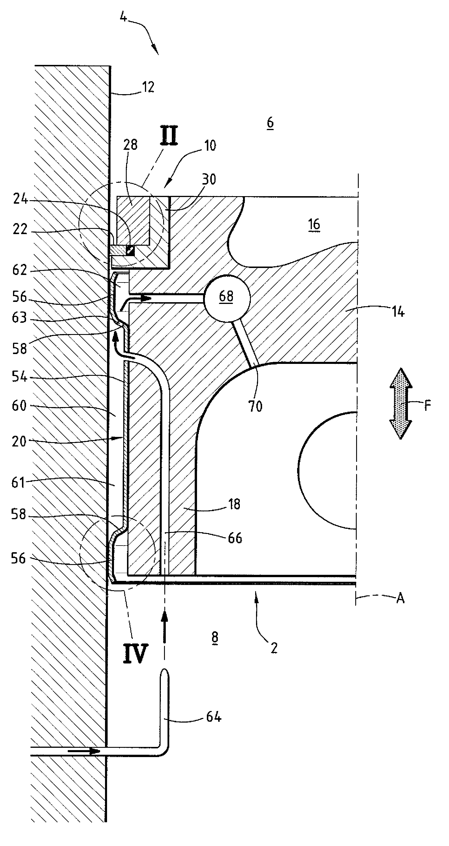
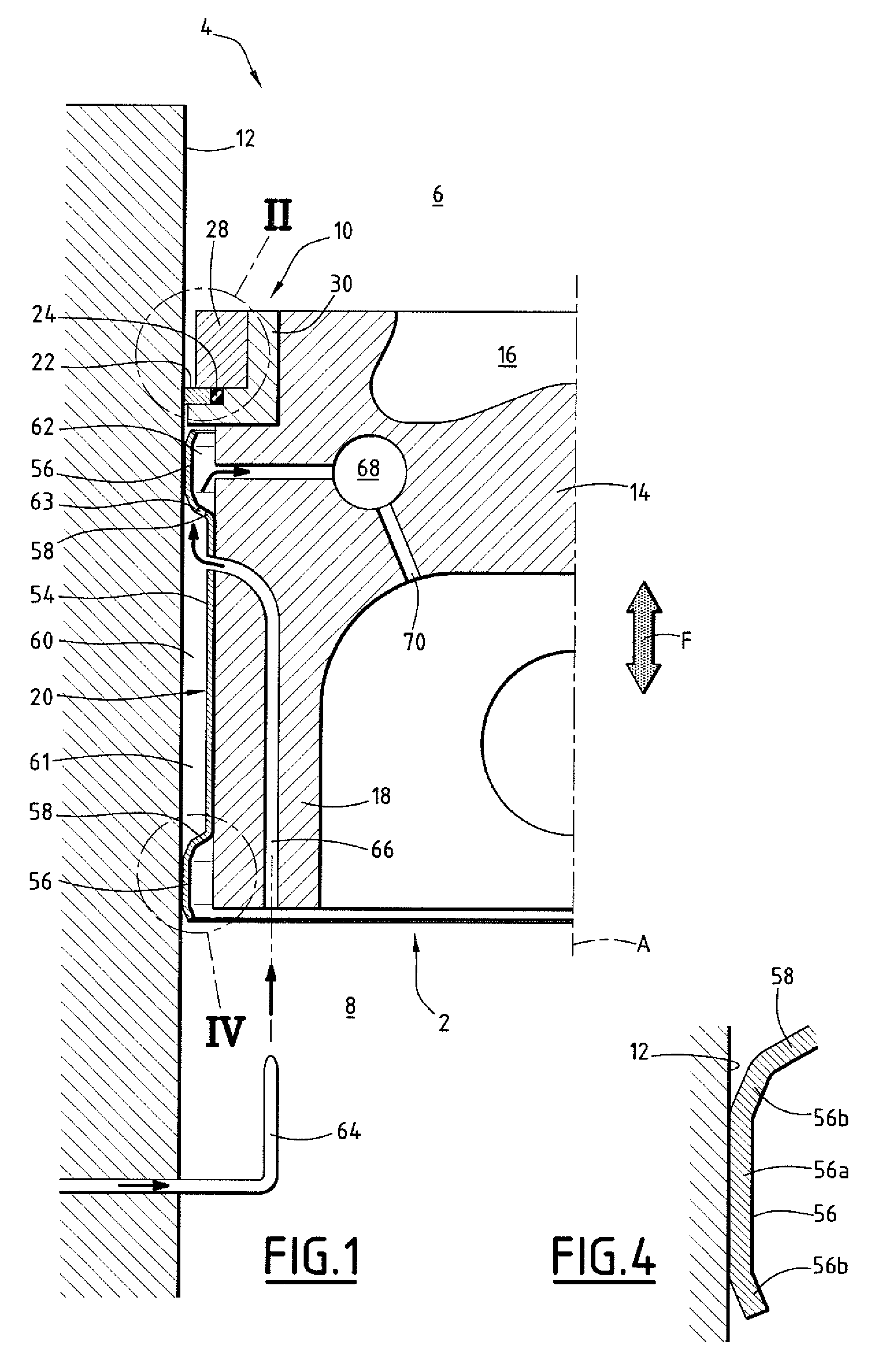
[0075]As illustrated in FIG. 1, piston 2 is movably mounted within chamber 4 of the internal combustion engine, moving in alternating linear motion (Arrow F) along an axis A.

[0076]Piston 2 separates chamber 4 in a leak tight manner into an upper high pressure volume 6 designed to receive air and fuel with a view to combustion, in a manner which is in itself known, and a lower low pressure volume 8 designed to be in communication with a crankcase containing a reserve of engine lubricating oil.

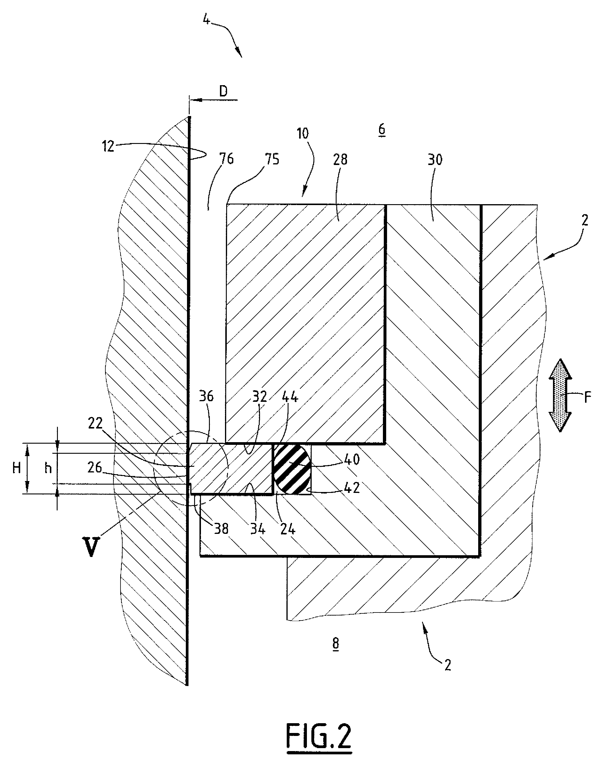
[0077]A sealing device 10 is located between piston 2 and sliding surface 12 partly bounding chamber 4. Surface 12 is circular and cylindrical and has an axis A.

[0078]Piston 2 comprises a body 14 in which there is a combustion recess 16 opening towards volume 6, a skirt 18 extending axially from body 14 towards volume 8, and a tubular jacket 20 guiding piston 2 along surface 12, integral with the external surface of skirt 18.

[0079]As illustrated in FIG. 2, sealing device 10 comprises a metal sea...


PUM


Abstract

This device is designed for a piston which is designed to move in alternating linear movement parallel to the axis of a chamber divided by the piston into a high pressure volume and a low pressure volume, and is of the type comprising:a circular cylindrical sliding surface bounding the chamber,an annular groove provided in the piston which is coaxial with the sliding surface and open towards the sliding surface, anda closed resilient sealing ring housed in a leak tight manner in the groove and intended to make sealing contact with the sliding surface.According to one aspect of the invention the ring is designed to determine the size of a lubricating oil film between the ring and the sliding surface to a limit lubricating thickness preferably from 0.1 μm to 1 μm when it moves from the high pressure volume to the low pressure volume.

Description

CROSS-REFERENCE TO RELATED APPLICATIONS[0001]This application is a continuation-in-part of application Ser. No. 11 / 566,369, filed on Dec. 4, 2006; which claims benefit of U.S. Provisional Application No. 60 / 742,880, filed on Dec. 7, 2005 (both of which are hereby incorporated by reference).FIELD OF THE INVENTION[0002]This invention relates to a sealing device for a piston designed to move in alternating linear motion parallel to one direction in a chamber divided by the piston into a high pressure volume and a low pressure volume, of the type comprising:[0003]a circular cylindrical sliding surface having an axis parallel to the direction of movement of the piston,[0004]an annular groove coaxial with the sliding surface, which opens towards the sliding surface,[0005]one of the sliding surface and the groove being of one piece with the piston and the other with the chamber, and[0006]a resilient closed sealing ring housed in a leak tight manner in the groove, and in sealing contact wit...

Claims


Application Information

Patent Timeline
Patent Type & Authority Patents(United States)
IPC IPC(8): F01B31/10
CPCF16J9/063F16J1/08
Inventor MELCHIOR, JEAN FREDERIC
Owner MELCHIOR
Why Eureka
Try Eureka