Hydronic system control for heating and cooling

Inactive Publication Date: 2010-06-08
CARRIER CORP
View PDF12 Cites 36 Cited by
  • Summary
  • Abstract
  • Description
  • Claims
  • Application Information

AI Technical Summary

Benefits of technology

[0008]The above and other objects are achieved by providing a two-pipe hydronic system with control logic, which continually polls the spaces or zones in which heating or cooling may be demanded so as to determine whether there is a predominance of either heating or cooling being demanded. The polling also checks to see whether a determined predominance of demand for either heating or cooling meets certain minimum demand requirements. In the event that minimum demand requirements are met, then a system demand is set reflecting the polling results. For instance, the system demand would be set for heated water if the predominance of polled spaces reflected that more spaces requested heating than requested cooling and that the number of spaces requesting heating exceeded some minimum number of spaces required to implement a changeover from cooling to heating. The system demand does not, however, allow for an immediate changeover to heating in the event t

Problems solved by technology

The system demand does not, however, allow for an immediate changeover to heating in the event that a changeover to heating is being requested by the polling results.

Method used


Image

  • Hydronic system control for heating and cooling
  • Hydronic system control for heating and cooling
  • Hydronic system control for heating and cooling

Examples


Embodiment Construction

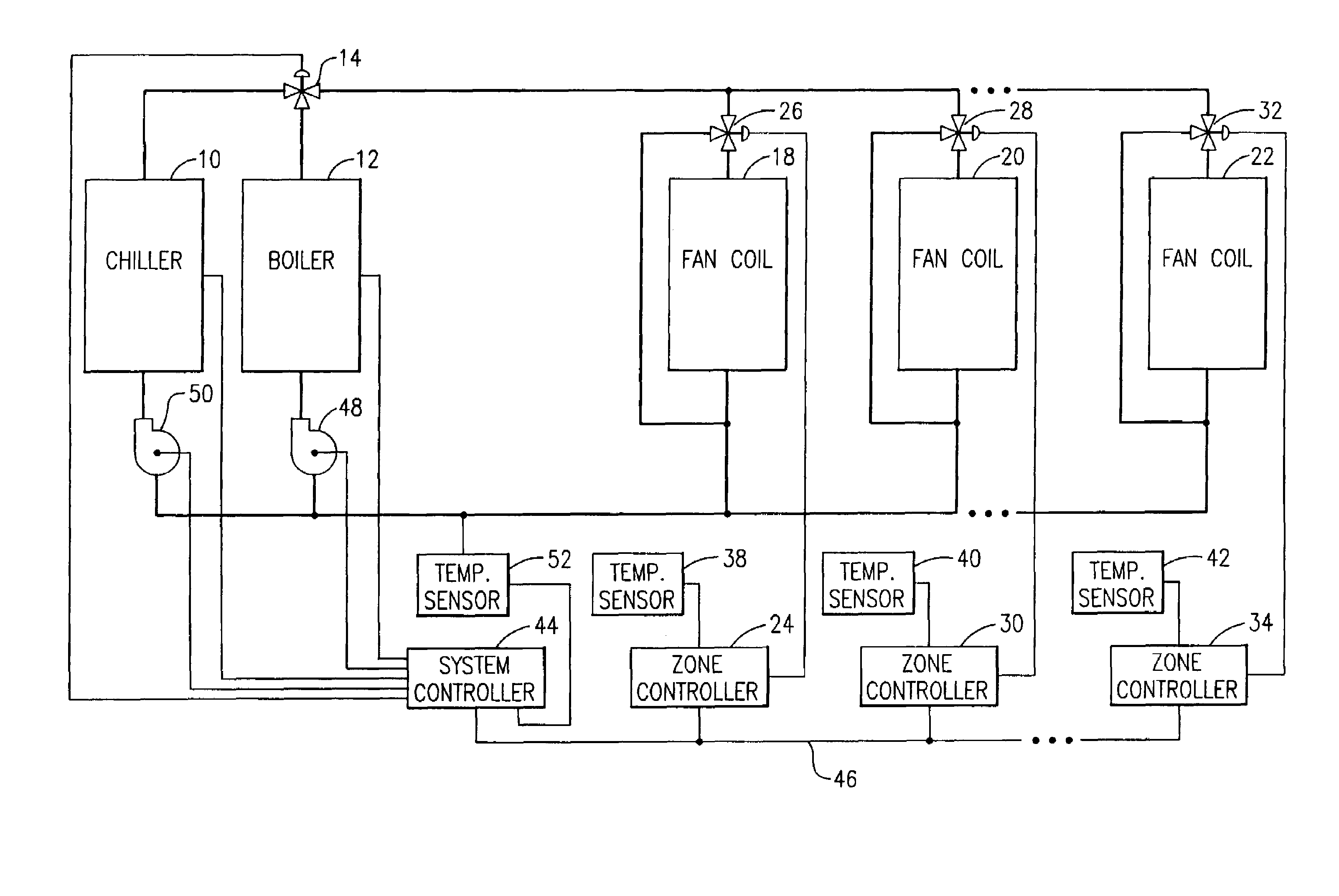
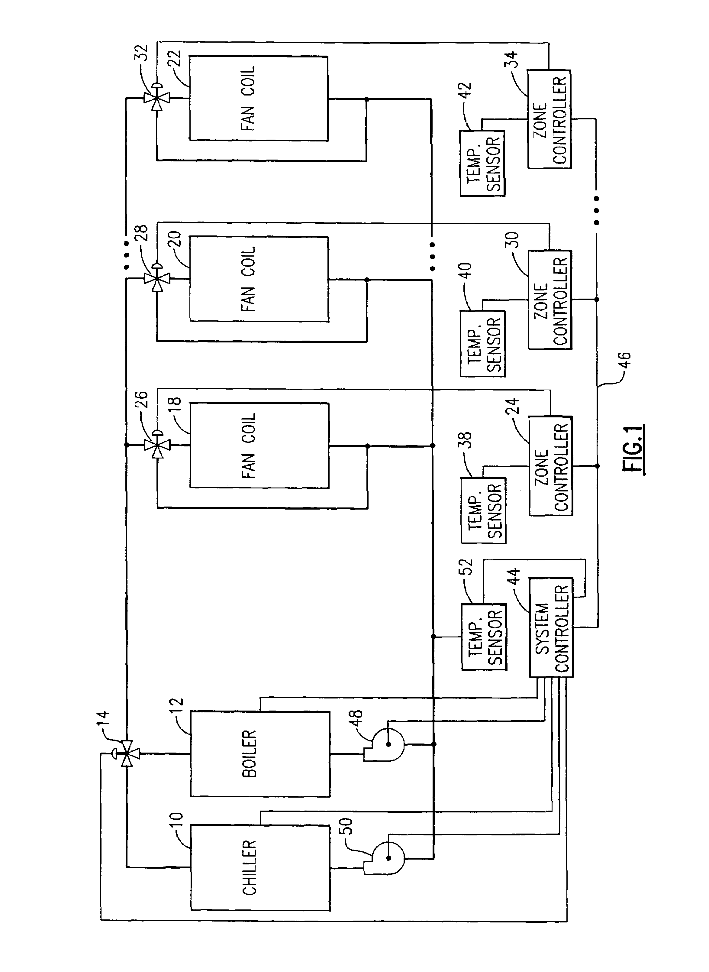
[0012]Referring now to FIG. 1, a two-pipe hydronic system is seen to include a chiller 10 and a boiler 12. Hot water from the boiler 12 may flow through a two-position changeover valve 14 to fan coil heat exchanger 18, 20 and 22. Alternatively, the chiller 10 may provide chilled water to the fan coil heat exchangers 18, 20 and 22 via the two position valve 14. It is to be understood that each fan coil heat exchanger may use the delivered water to condition air in a space that is to be heated or cooled. This is often referred to as a “zone of heating or cooling”. Water from either the chiller 10 or the boiler 12 flows through the fan coil heat exchanger 18 in the event that a zone controller 24 authorizes such a flow by positioning of a control valve 26. The zone controller 24 may also divert any water flow around the fan coil heat exchanger 18 by a further positioning of the control valve 26. It is to be appreciated that the fan coil heat exchanger 20 operates in a similar fashion i...


PUM


Abstract

A control system for controlling delivery of either heated or cooled water over a common water line to a plurality of heat exchangers. The control system includes a hydronic system controller which polls the heating or cooling demands of zone controllers controlling the respective delivery of water to the individual heat exchangers. The hydronic system controller is operative to implement a changeover between delivery of heated water to delivery cooled water or vice versa. The implemented changeover preferably includes checking the temperature of the water being returned to the source or sources for heating or cooling the water as well as defining a changeover time period which must occur in the event that the temperature of the water in the return line is not within a predefined range.

Description

BACKGROUND OF THE INVENTION[0001]This invention relates to systems for adding or removing heat from a confined space in order to control the temperature in that space. In particular, this invention relates to hydronic systems which employ water as the heat exchange medium for adding or removing heat from a confined space.[0002]Hydronic systems may employ different approaches as to how to deliver water to spaces that are to be heated or cooled. For instance, hydronic systems may use a first conduit to deliver heated water and a second conduit to deliver cooled water to one or more heat exchangers servicing the spaces to be heated or cooled. These systems will also use separate return conduits to circulate the water back to the heating and cooling sources which heat or cool the water before it is again delivered to the one or more heat exchangers. The above described hydronic systems are often referred to as “four pipe” hydronic systems because there are two delivery conduits or pipes...

Claims


Application Information

Patent Timeline
IPC IPC(8): F24F3/06F24F11/00
CPCF24F3/06F24F11/006F24F2221/54F24F2011/0064F24F2011/0045F24F11/30F24F2140/20F24F11/62F24F11/65F24F11/84
Inventor BUJAK, JR., WALTER E.
Owner CARRIER CORP
Why Eureka
Try Eureka