Closure assembly with breakaway sealing portion with gripping tab

a technology of sealing portion and closure assembly, which is applied in the direction of closure lids, closure stoppers, containers, etc., can solve the problems of not being able to remove this type of lids, frequent accidents with fingers, and inconvenience for the same applicant, so as to achieve simple construction and reduce costs

Inactive Publication Date: 2010-06-08
BRASILATA S A EMBALAGENS METALICAS
View PDF69 Cites 54 Cited by
  • Summary
  • Abstract
  • Description
  • Claims
  • Application Information

AI Technical Summary

Benefits of technology

[0010]It is a generic object of the present invention to provide a reclosable plastic lid for a can of the type considered herein, which presents a simple construction and reduced cost, incorporating means for facilitating the opening thereof and also a reliable seal of prompt visual indication of violation.
[0011]It is a further object of the present invention to provide a plastic lid such as defined above, which can be safely and easily handled by the consumer.SUMMARY OF THE INVENTION

Problems solved by technology

This inner seal is only visible when the lid is removed and it also requires the use of an instrument for cutting it peripherally, which invariably leaves cutting edges close to the upper opening of the can, causing frequent accidents with wounds in the user's fingers.
It is not possible for the user to remove this type of lid by using his hands only.
While it eliminates the deficiencies of the prior lids for cans containing products of progressive consumption, this prior solution of the same applicant still presents some inconveniences.
One of said inconveniences relates to the questionable reliability of the retention of the seal strip, as it can be removed if carefully forced upwardly, sliding out from the upper double seam of the can.
Another inconvenience of said prior art lid results from the fact that the opening thereof, by axially pulling it by means of the opposite handles, is abrupt, provoking an undue discharge of the stored product when the lid is removed.

Method used


Image

  • Closure assembly with breakaway sealing portion with gripping tab
  • Closure assembly with breakaway sealing portion with gripping tab
  • Closure assembly with breakaway sealing portion with gripping tab

Examples


Embodiment Construction

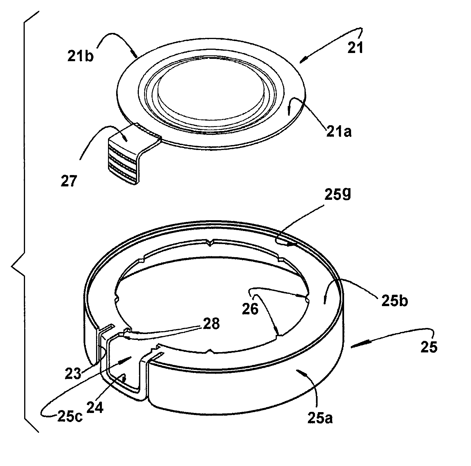
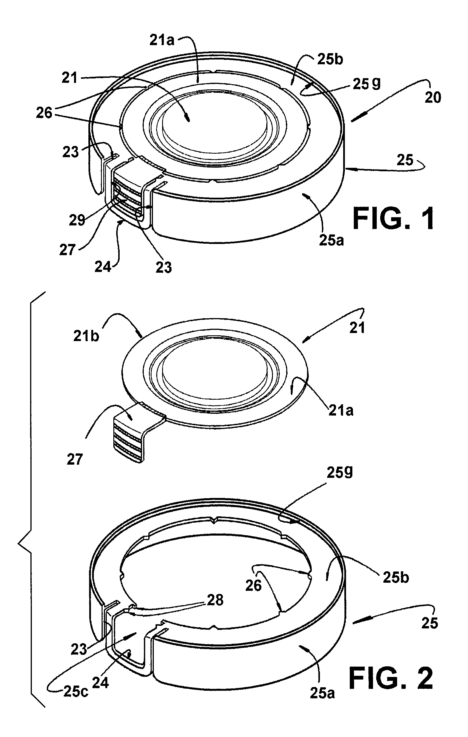
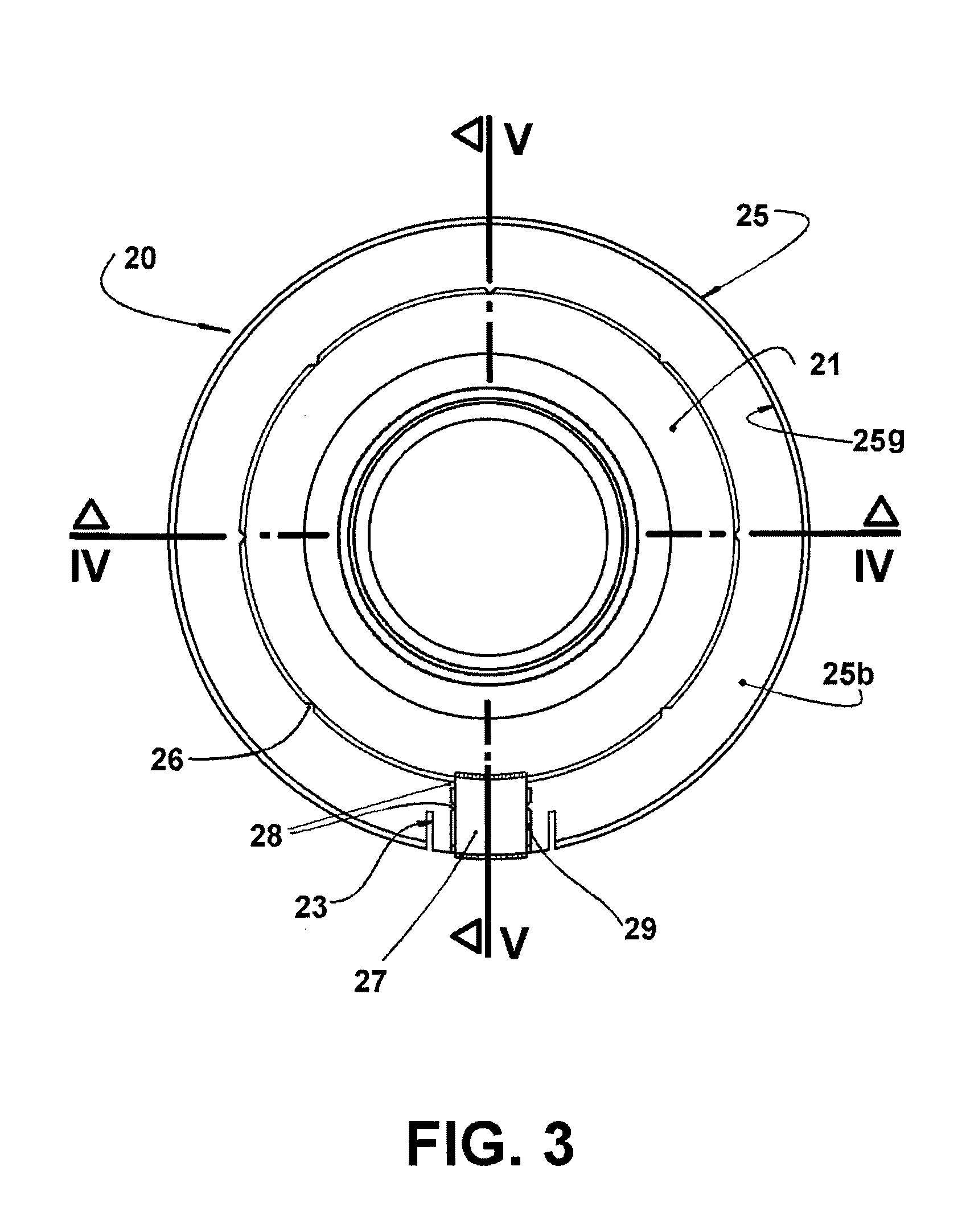
[0025]According to the embodiments illustrated in FIGS. 1-10, the present lid is applied to a can made of a metallic sheet, comprising a tubular body 10 with a lower end 11 affixing a bottom wall 12, and with an upper end 13 affixing, by double seaming, an annular upper wall 14, which defines, internally, a seat 15 for the hermetic seating of the lid 20.

[0026]The annular upper wall 14 can take the form of a structural ring, as illustrated in FIGS. 4, 5, 9, and 10, or even in the form of an annular plate in the cans with great dimensions, such as the 18-liter cans. The construction of the annular upper wall 14 and of the seat 15 may be achieved by different manners, provided that it allows a hermetic and safe fitting of the lid 20 to the upper part of the can. In FIGS. 4, 5, 9 and 10, the construction of the annular upper wall 14 and of the seat 15 is accomplished as described and claimed in the Brazilian patent PI 9408643-5 issued to the same applicant in Brazil and in other countri...


PUM


Abstract

A plastic lid for a can of the type comprising a tubular body (10) having an upper end (13) for the seating of the lid (20) comprising a sealing portion (21), removably seated on the tubular body (10) and provided with an upper edge (21b), a seal portion (25), to be ruptured upon the first opening of the lid (20), having an upper ring (25b) which is incorporated to a lower skirt (25a), said upper ring (25b) and said lower skirt (25a) being respectively seated onto and around part of the upper end (13), said upper ring (25b) being incorporated through radial bridges (26), to said upper edge (21b), the seal portion (25) presenting an interruption (25c) extending through the width of the upper ring (25b) and through at least part of the height of the lower skirt (25a). The sealing portion (21) incorporates a gripping tab (27) which is manually operable only when part of the seal portion (25) is ruptured.

Description

CROSS-REFERENCE TO PRIOR APPLICATIONS[0001]This is a U.S. National Phase application under 35 U.S.C. §371 of International Patent Application No. PCT / BR03 / 00030 filed Mar. 6, 2003, and claims the benefit of Brazilian Patent Application Nos. PI 0201981-7 filed Mar. 7, 2002 and PI 0203950-8 filed Sep. 6, 2002. The International Application was published in English on Sep. 12, 2003 as WO 2003 / 074381 A1 under PCT Article 21(2).FIELD OF THE INVENTION[0002]The present invention refers to a plastic lid for the closure of a can made of a metallic sheet and of the type comprising a tubular body, with the lower edge affixing or incorporating a bottom wall and with the upper edge carrying, directly by means of a deformed portion of the tubular body or by means of an annular upper wall portion that can take the form of a structural ring, a seat for the seating and retention of the press-fittable lid. Particularly, the invention refers to the provision of a plastic lid for a can of the type cons...

Claims


Application Information

Patent Timeline
Patent Type & Authority Patents(United States)
IPC IPC(8): B65D17/34B65D17/40B65D51/20B65D47/36B65D1/00B65D21/02B65D39/02B65D43/02B65D43/04
CPCB65D21/0219B65D43/0254B65D2543/00092B65D2543/00296B65D2543/00435B65D2543/00509B65D2543/00842B65D2543/00546B65D2543/00555B65D2543/00638B65D2543/00685B65D2543/00731B65D2543/00796B65D2543/00537B65D21/02B65D41/32B65D43/02
Inventor TEIXEIRA ALVARES, ANTONIO CARLOSSENE, ANTONIO ROBERTO
Owner BRASILATA S A EMBALAGENS METALICAS
Why Eureka
Try Eureka