
Contact lens mold assemblies and systems and methods of producing same

a technology of contact lens and mold parts, which is applied in the direction of foundation moulding apparatus, mechanical vibration separation, instruments, etc., can solve the problems of deformation or deterioration, deformation of mold sections, and increased waste of precursor materials, so as to prevent cavitation of unpolymerized lens materials

Active Publication Date: 2010-06-08
COOPERVISION INT LTD
View PDF57 Cites 24 Cited by
  • Summary
  • Abstract
  • Description
  • Claims
  • Application Information

AI Technical Summary

Benefits of technology

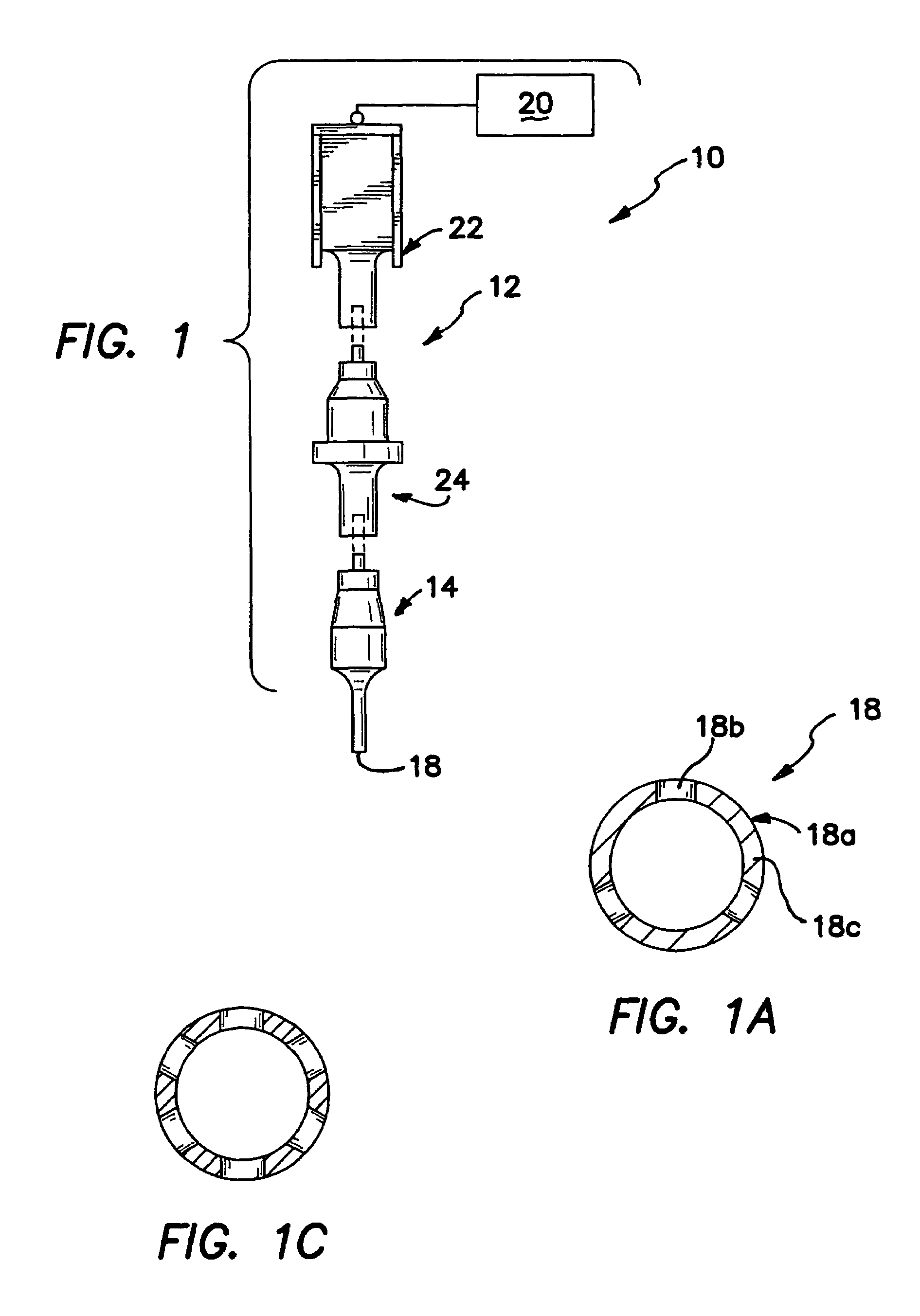
[0015]The systems and methods are suitable for automated manufacture of contact lenses, such as silicone hydrogel contact lenses, including daily wear and extended or continuous wear lenses. For example, the present systems can fill contact lens mold sections using an assembly including a removable, replaceable UV blocking reservoir that holds a relatively large amount of contact lens precursor materials, and a dispense mechanism directly connected to the reservoir that holds a relatively smaller amount of the contact lens precursor materials. The reservoir may be the barrel of a syringe. A diaphragm valve may be operably located between the reservoir and the dispense assembly. The dispense mechanism includes a dispense tip. A conveyor is provided for passing unfilled mold sections beneath the dispense mechanism. A stepper motor may be used to cause the dispense mechanism to automatically dispense a substantially precise and accurate amount of precursor composition from a dispense tip into each desired lens cup that passed beneath the dispense tip. When the dispense apparatus is empty, a valve is opened between the reservoir and dispense mechanism connected thereto to refill the dispense mechanism. When the reservoir itself becomes empty, the reservoir can be easily and quickly replaced by a filled reservoir.
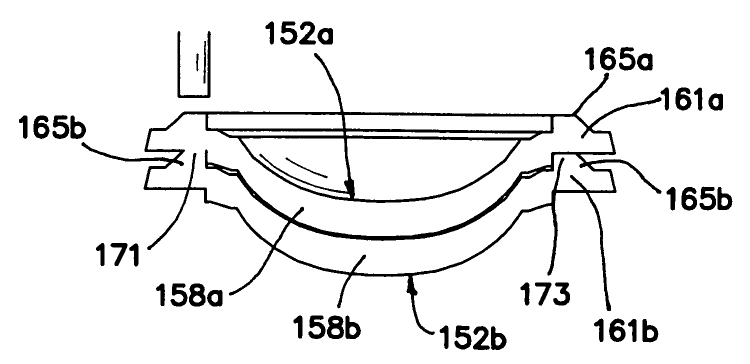
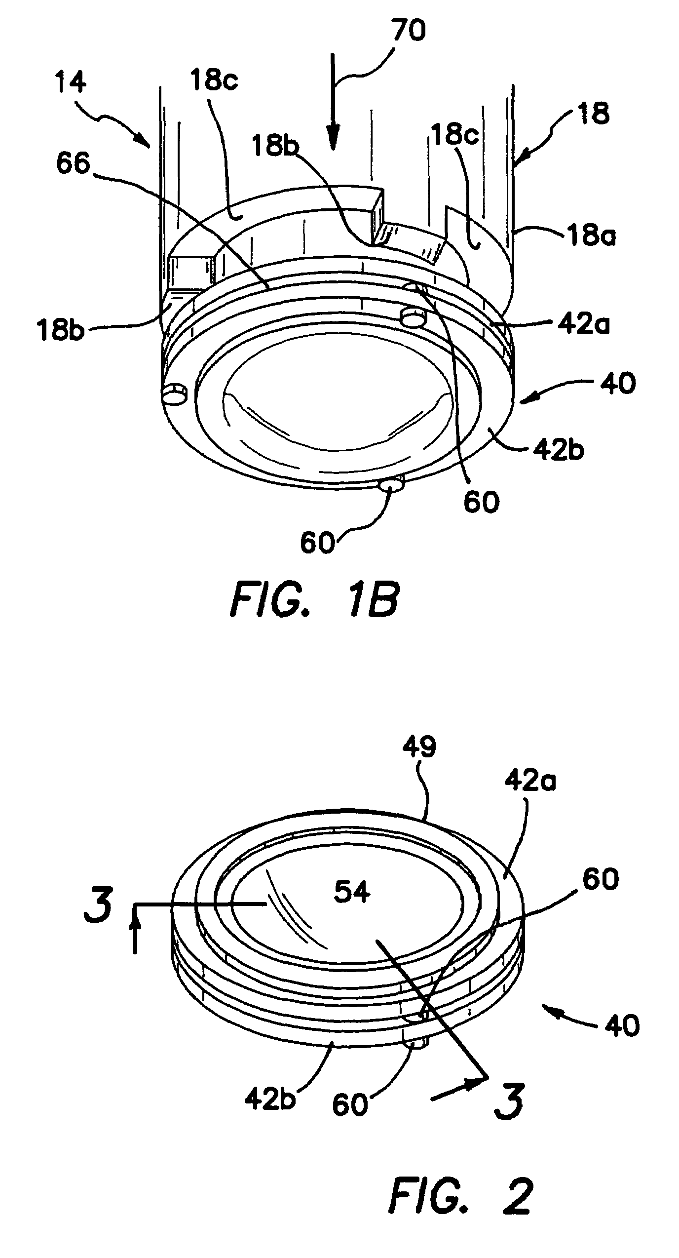
[0033]The projections are effective in facilitating fusion of the mold sections by providing discrete contact regions between the mold section to which vibrational energy will be effectively focused.
[0041]When two of such mold sections having such recessed regions are assembled together to form a mold assembly, the recessed regions provide gaps dividing contact region between the mold sections. Although not wishing to be bound by any specific theory of the invention, the gaps may be advantageous in preventing cavitation of unpolymerized lens material during the ultrasonic fusion step, possibly by allowing gasses to escape from between interfacing, unfused flange surfaces. Other benefits may also be achieved by the presence of gaps in the contact regions.

Problems solved by technology

This method is labor intensive, presents substantial risks to people handling the precursor material, and can result in increased waste of the precursor material since large volumes of the material remain in the jar for extended periods of time, which can degrade or deteriorate over time.
The mold sections are often destroyed during this removal step.
One obstacle associated with cast molding processes is the appropriate placement and fixation of the mold sections, particularly after the lens precursor material has been placed between the mold sections and prior to polymerization thereof.
For example, it may be difficult to secure two mold sections together to form a mold assembly without opacification, pitting, or bubble formation in the lens cup (e.g., the region of the mold section containing the lens precursor material).
Further, it may also be difficult to form a mold assembly in which the lens precursor material has a substantially uniform thickness, or in other words the lens does not have an undesired prism due to thickening of the lens precursor material at one region of the lens cup relative to another different region.
In addition, because of the potentially fragile nature of the polymerized contact lens product, the mold sections should be separable without causing breakage of or damage to the lens product.
While this may be a somewhat acceptable practice on a small scale production basis, it may not satisfy all of the requirements of large scale and / or automated high speed manufacturing production of contact lenses.

Method used


Image

  • Contact lens mold assemblies and systems and methods of producing same
  • Contact lens mold assemblies and systems and methods of producing same
  • Contact lens mold assemblies and systems and methods of producing same

Examples


Embodiment Construction

[0063]The present invention will typically be described herein with respect to methods and systems useful for the manufacture of contact lenses, though it is to be appreciated that, with appropriate modification thereto, the present methods and systems may be useful for the manufacture of other types of ophthalmic lenses and other light-polymerizable articles in general. In a preferred embodiment, the present systems, methods, and components thereof are useful in manufacturing silicone hydrogel contact lenses, or contact lenses that comprise a silicone hydrogel material. For example, the present systems, methods, and components thereof may be particularly useful in producing extended wear silicone hydrogel contact lenses, and / or daily wear silicone hydrogel contact lenses.

[0064]In a broad aspect of the invention, methods of making contact lenses are provided, the methods generally comprise at least one of the following steps of providing first and second mold sections, each mold sec...


PUM

PropertyMeasurementUnit
volumeaaaaaaaaaa
volumeaaaaaaaaaa
volumeaaaaaaaaaa

Abstract

Methods and apparatus are provided for making an ophthalmic lens. Apparatus are provided for filling contact lens shaped cavities of contact lens molding assemblies. Methods of coupling and fusing contact lens mold sections are also provided and generally include providing first and second mold sections which, when coupled together, are effective to form a lens-shaped cavity and contact regions between the mold sections. One or both of the mold sections may include one or more recessed regions or projections which provide areas of non-fusion and areas of fusion, respectively, when the mold sections have been filled with a contact lens precursor material and are fused together, for example, by focused ultrasound energy.

Description

[0001]The present invention generally relates to devices, systems, and methods for producing contact lenses, such as silicone hydrogel contact lenses, or contact lenses that comprise a silicone hydrogel material. More particularly, the invention relates to systems for providing polymerizable compositions to mold sections systems for fusing mold sections together to form mold assemblies, and mold assemblies produced therefrom.BACKGROUND[0002]One method of manufacturing ophthalmic lenses, such as intraocular lenses and contact lenses, is by cast molding.[0003]Cast molding of contact lenses is well known. See, for example, Appleton, et al., U.S. Pat. No. 5,466,147, Morris, U.S. Pat. No. 6,405,993, and Dean, U.S. Pat. No. 6,732,993.[0004]Typically, a single mold assembly for molding a single contact lens product includes a female mold section having a concave optical surface defining an anterior surface of a lens to be made, and a male mold section having a convex optical surface defini...

Claims


Application Information

Patent Timeline
Patent Type & Authority Patents(United States)
IPC IPC(8): B29D11/00G02B1/08
CPCB29D11/00038B29D11/0049Y10S425/808B29D11/00125B29D11/00
Inventor DARNTON, SARAH E.GOODENOUGH, NEIL G.ROGERS, RICHARD C.
Owner COOPERVISION INT LTD
Learn More