
Revolving door control system

a control system and door technology, applied in the direction of computer control, program control, securing communication, etc., can solve the problems of mat failure, mat cannot detect a person or object, and traps the unauthorized person in the chamber

Inactive Publication Date: 2010-06-08
BEA INC
View PDF13 Cites 13 Cited by
  • Summary
  • Abstract
  • Description
  • Claims
  • Application Information

AI Technical Summary

Benefits of technology

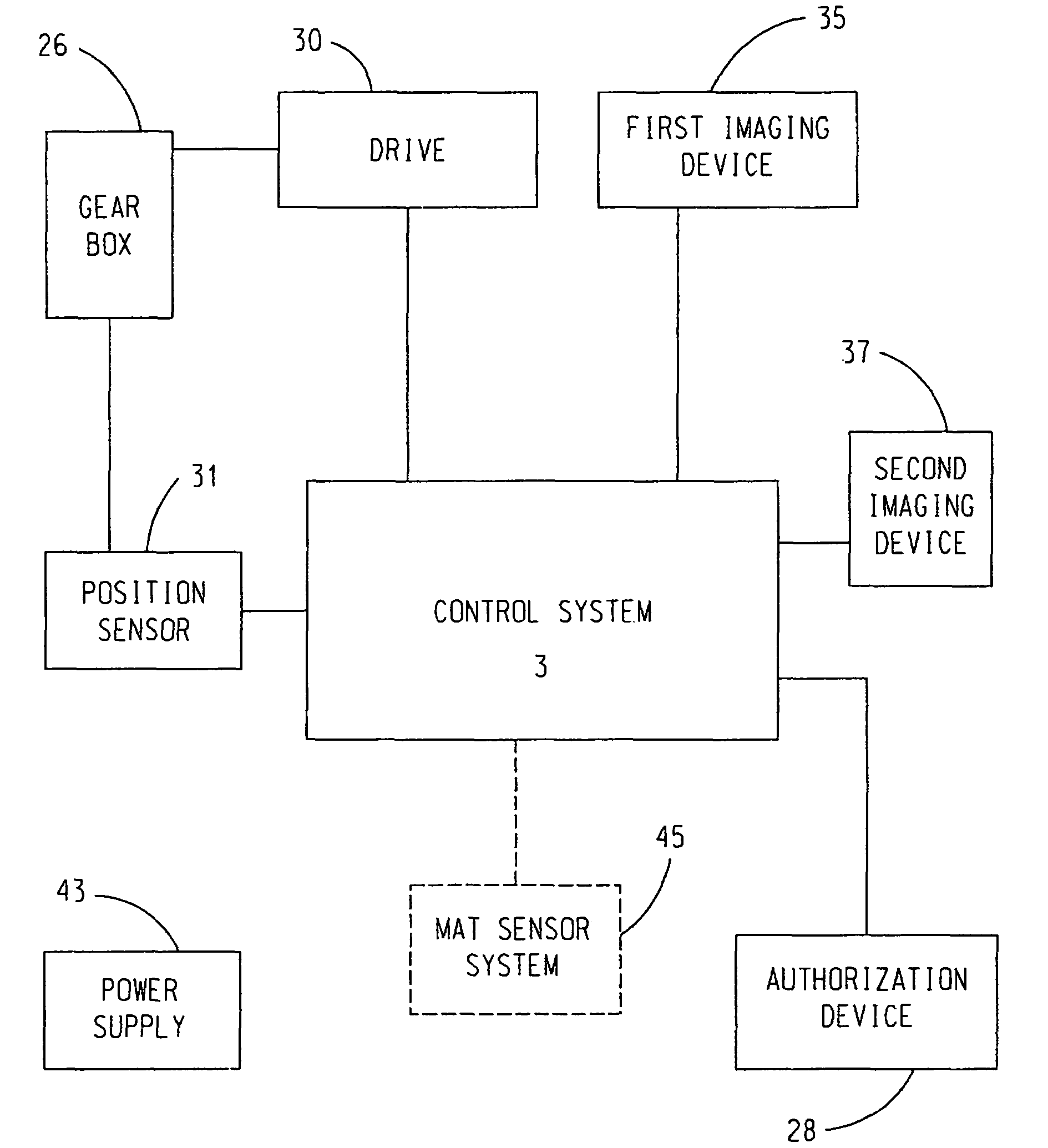
"The invention is a method and control system for controlling a revolving door. The method involves using infrared imaging sensors to detect the presence of objects in the housing of the door, and a drive system to rotate the door between openings. The control system can also include an authorization means to identify authorized users. The technical effect of this invention is to provide a more efficient and secure method for controlling revolving doors, allowing for better management of user access and preventing unauthorized individuals from entering the chambers."

Problems solved by technology

In such situations, prior art systems stop the door thereby trapping the unauthorized person in a chamber.
However, such mats have several drawbacks.
First, rain, snow, dirt or other foreign matter can often cause mat failures.
Second, a mat cannot detect a person or object such as a gun or a security pass card attached to the door frame.
Third, it is difficult to make a mat sufficiently sensitive to lightweight objects.
It has been proposed to use ultrasonic sensors instead of mats, but use of such sensors in a revolving door presents problems.
Second, it is well known that ultrasound waves used by ultrasound sensors are susceptible to distortion by moving air which can be caused either by rotation of the door in use or by a flow of air through the door caused by the difference in positive air pressure inside a building in which the door is installed due to the operation of the buildings' HVAC system and a lower air pressure outside the building.
Such movement of air can distort the ultrasound waves rendering detection of objects or persons difficult.
Such high gain increases the likelihood that reverberations or echoes will cause false readings.
Similarly, the greater the range (portion of the floor to ceiling distance) covered by the sensor, the greater the likelihood of false readings due primarily to echoes from the floor.
Furthermore, such sensors do not have the ability to distinguish between an actual object or person located in one of the compartments and on one of the door wings.

Method used


Image

  • Revolving door control system
  • Revolving door control system
  • Revolving door control system

Examples


Embodiment Construction

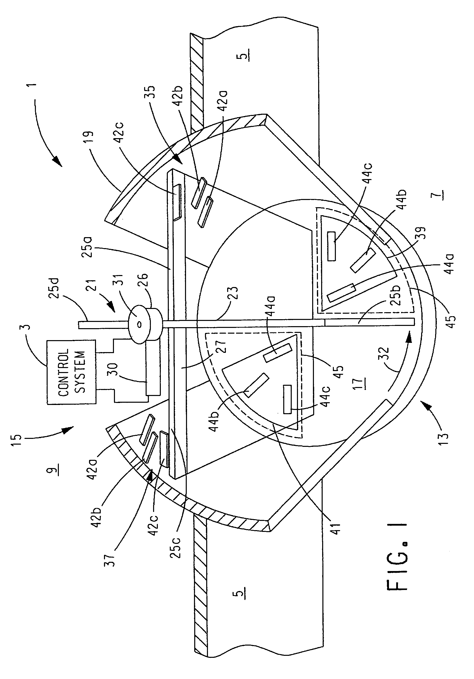
[0033]The present invention will be described with reference to the accompanying figures where like reference numbers correspond to like elements.

[0034]For purposes of the description hereinafter, the terms “upper”, “lower”, “right”, “left”, “vertical”, “horizontal”, “top”, “bottom”, “lateral”, “longitudinal” and derivatives thereof shall relate to the invention as it is oriented in the drawing figures. However, it is to be understood that the invention may assume various alternative variations, except where expressly specified to the contrary. It is also to be understood that the specific devices illustrated in the attached drawings, and described in the following specification, are simply exemplary embodiments of the invention. Hence, specific dimensions and other physical characteristics related to the embodiments disclosed herein are not to be considered as limiting.

[0035]With reference to FIG. 1, a revolving door 1 with a control system 3 is incorporated into a wall 5 which sep...


PUM


Abstract

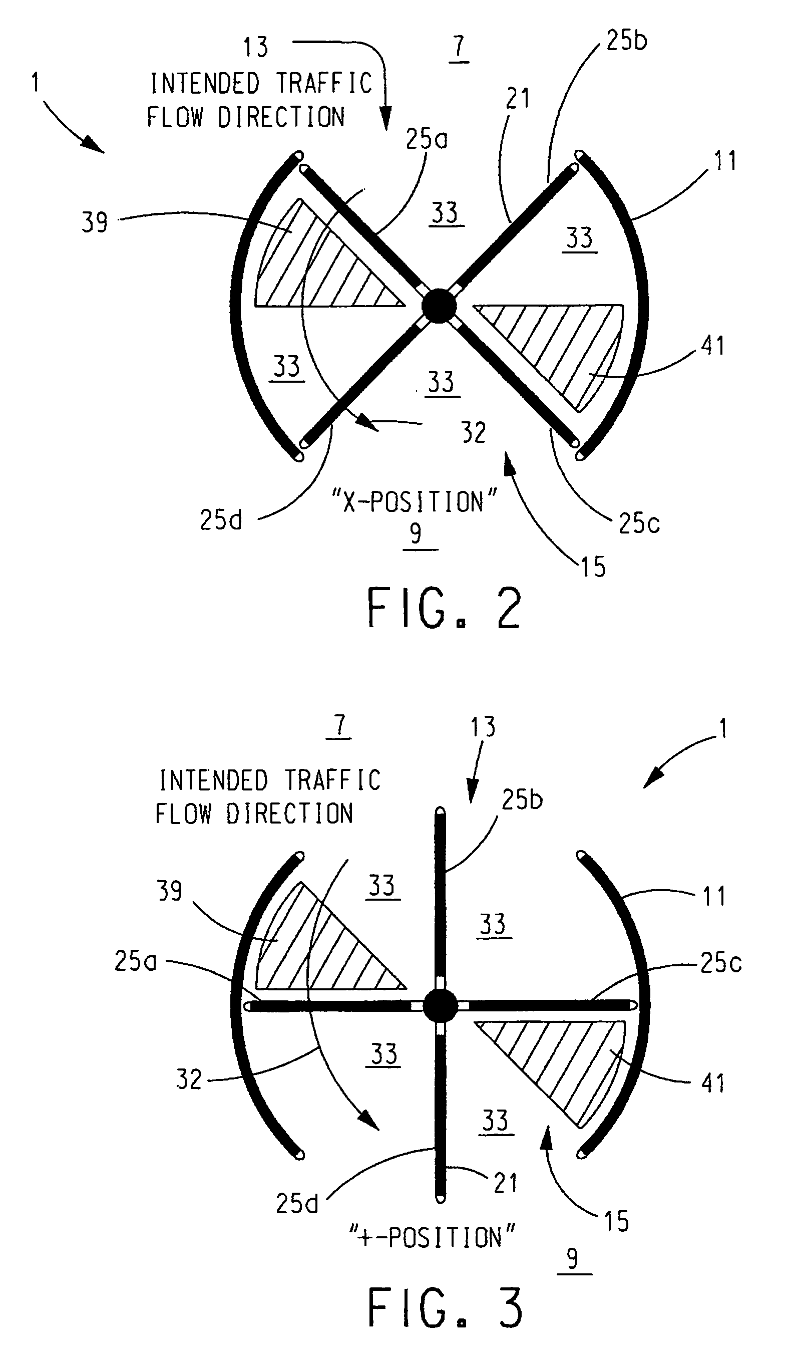
In a method and system for controlling a revolving door that has a plurality of chambers defined by wings of a revolver, at least one imaging sensor is provided for acquiring images of a first area where the plurality of chambers rotatably pass by or through. A drive causes the revolver to rotate in a first direction from a first position where a user can enter a first chamber via the first opening. Images are acquired by the one imaging sensor and signals are acquired from a position sensor that is operative for outputting signals indicative of the angular position of the revolver. Based on the signals acquired from the position sensor, each imaging sensor or its output is disabled and / or each image acquired by each imaging sensor is ignored when each door wing is in field-of-view of the imaging sensor.

Description

CROSS REFERENCE TO RELATED APPLICATIONS[0001]This application claims the benefit of U.S. Provisional Patent Application No. 60 / 816,768, filed Jun. 27, 2006, which is incorporated herein by reference in its entirety.BACKGROUND OF THE INVENTION[0002]1. Field of the Invention[0003]The present invention relates to revolving security doors and so-called, man-traps.[0004]2. Description of Related Art[0005]Security doors and, so-called man-traps (hereinafter individually and collectively referred to as “security doors” or “security door”) are used in airports, banks, commercial buildings, military installations, and other locations where restricted access is desirable. In many instances, such security doors are embodied as revolving doors. In a common, non-limiting, embodiment of a revolving security door, a person inserts a pass card into a card reader that is interfaced with a control system for the door, and enters a chamber on one side of the door. If the card is authorized, the door w...

Claims


Application Information

Patent Timeline
Patent Type & Authority Patents(United States)
IPC IPC(8): H02P8/06H02P8/08
CPCE05G5/003E05F15/608E05F15/74E05Y2400/334E05Y2600/458E05F2015/767E05Y2900/132
Inventor CASELLA, ZACHARY T.STADLER, MICHAEL F.SCHLUEP, THOMAS P.
Owner BEA INC
Learn More