Multi-output type DC/DC converter
a multi-output type, converter technology, applied in the direction of process and machine control, instruments, packaged goods types, etc., can solve the problems of the difficulty of keeping the desired electric potential, the inability to intercept the signals input, etc., to prevent the output voltage from greatly shifting, and the effect of preventing production
- Summary
- Abstract
- Description
- Claims
- Application Information
AI Technical Summary
Benefits of technology
Problems solved by technology
Method used
Image
Examples
first embodiment
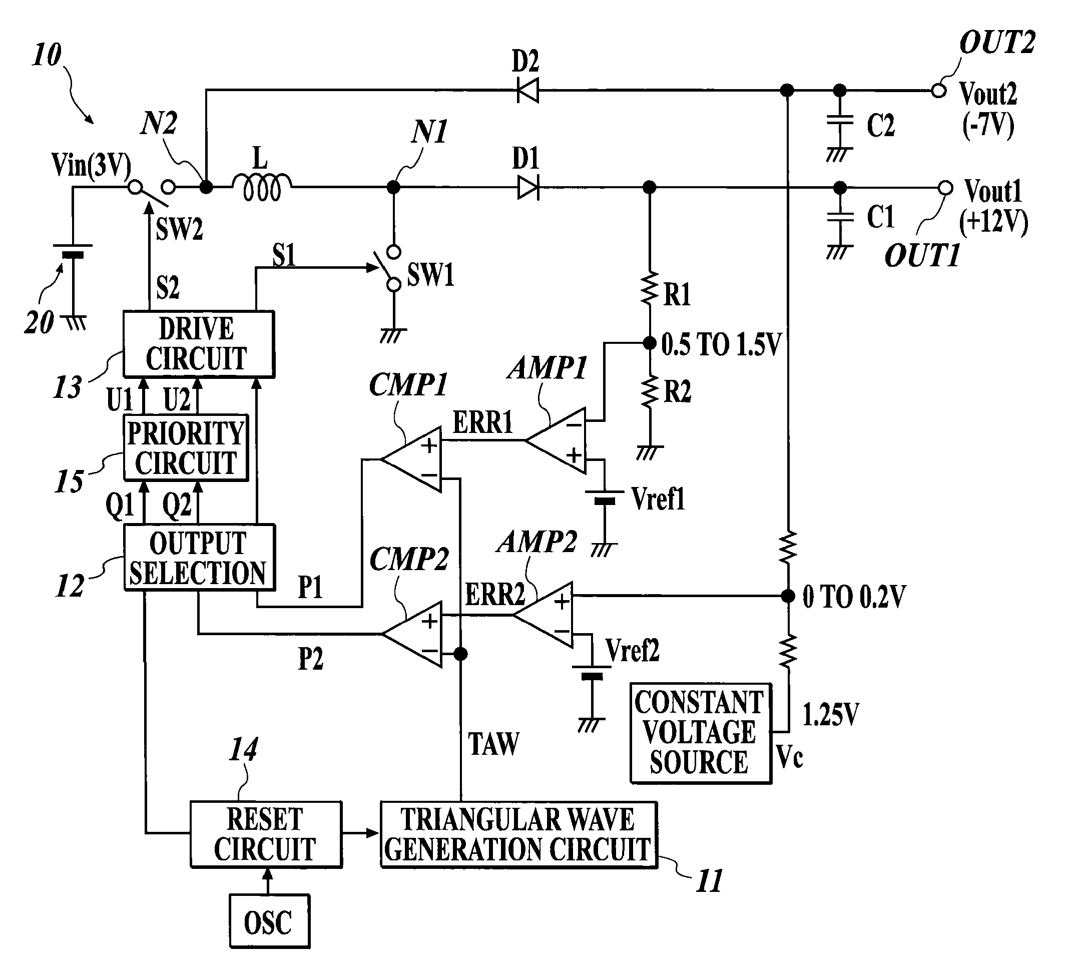
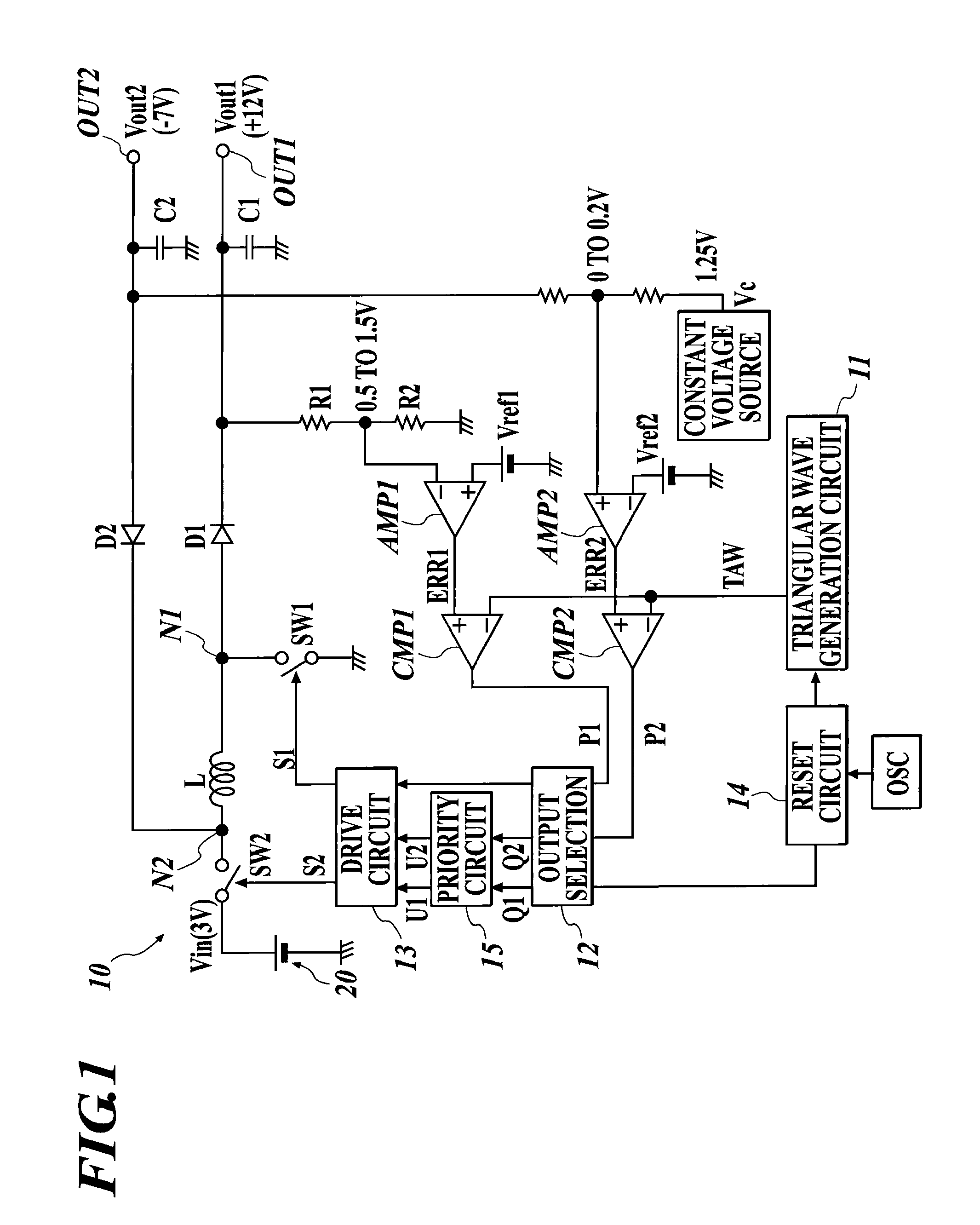
[0042]FIG. 1 is a configuration diagram showing a multi-output type DC / DC converter of the present invention.
[0043]The multi-output type DC / DC converter 10 of the embodiment is a boosting & inverting type converter. The boosting & inverting type converter turns on switches SW1 and SW2, which are constructed of transistors such as a MOSFET, to apply an input voltage Vin from a direct-current power supply 20 to a reactor L for flowing an current therethrough. The boosting & inverting type converter thus applies a current to flow on the output side from the reactor L to perform voltage output. The multi-output type DC / DC converter 10 outputs two kinds of output voltages Vout1 and Vout2 to two output terminals OUT1 and OUT2, respectively, by switching of the switches in the above boosting & inverting type converter.
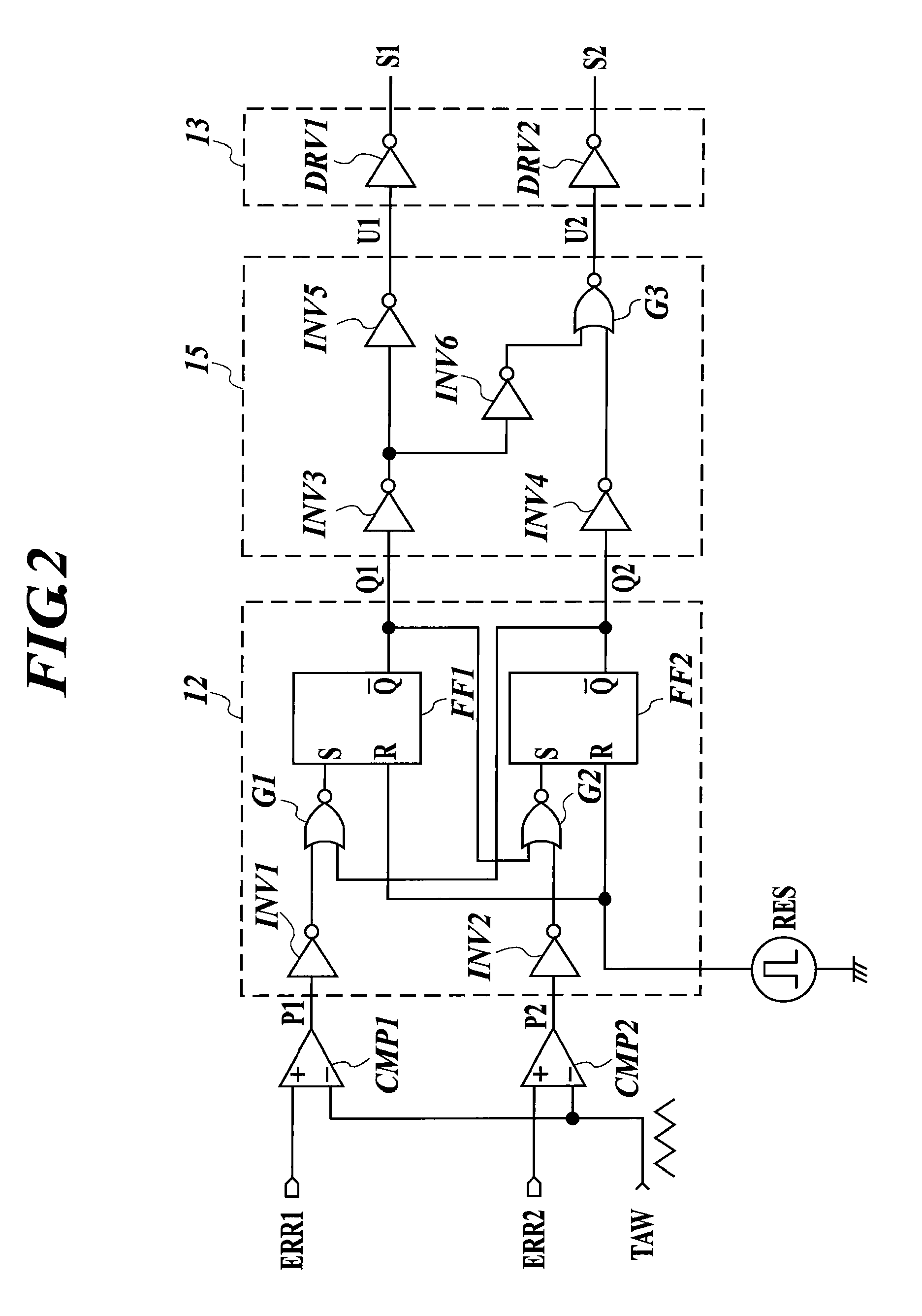
[0044]The multi-output type DC / DC converter 10 of the embodiment includes the reactor L accumulating electric energy, a switch SW2 provided between the direct-current power s...
second embodiment
[0064]FIG. 4 is a configuration diagram showing a multi-output type DC / DC converter of the present invention.
[0065]The multi-output type DC / DC converter 10 of the embodiment is a boosting & boosting type converter including a reactor L, a switch SW0 provided between the reactor L and the ground, which switch SW0 intermittently applies an input voltage Vin to the reactor L by the on-off action of the switch SW0 to accumulate energy in the reactor L, a first rectification & smoothing circuit 16a provided between the reactor L and a first output terminal OUT1, a second rectification & smoothing circuit 16b provided between the reactor L and the second output terminal OUT2, a switch SW1 connected between the reactor L and the first rectification & smoothing circuit 16a, and a switch SW2 connected between the reactor L and a second rectification & smoothing circuit 16b. Furthermore, the multi-output type DC / DC converter 10 includes a first detection circuit 17a detecting a first output v...
third embodiment
[0069]FIG. 5 is a configuration diagram showing a multi-output type DC / DC converter of the present invention.
[0070]The multi-output type DC / DC converter 10 of the embodiment is a boosting & stepping down type converter including a reactor L, a switch SW0 provided between a direct-current power supply 20, and the reactor L and the ground, which switch SW0 intermittently applies an input voltage Vin to the reactor L by the on-off action of the switch SW0 to accumulate energy in the reactor L, a switch SW3 provided between one terminal of the reactor L and the ground, a switch SW4 provided between the other terminal of the reactor L and the ground, a switch SW1 connected between the reactor L and a first rectification & smoothing circuit 16a, and a switch SW2 connected between the reactor L and a second rectification & smoothing circuit 16b.
[0071]The multi-output type DC / DC converter 10 of the embodiment can output a voltage obtained by boosting the input voltage Vin to the output ter...
PUM
 Abstract
Description
Claims
Application Information
 - R&D
- Intellectual Property
- Life Sciences
- Materials
- Tech Scout
- Unparalleled Data Quality
- Higher Quality Content
- 60% Fewer Hallucinations
Browse by: Latest US Patents, China's latest patents, Technical Efficacy Thesaurus, Application Domain, Technology Topic, Popular Technical Reports.
© 2025 PatSnap. All rights reserved.Legal|Privacy policy|Modern Slavery Act Transparency Statement|Sitemap|About US| Contact US: help@patsnap.com


