Receiver and electronic apparatus

a technology of electronic equipment and receiver, applied in the direction of digital transmission, pulse automatic control, transmission, etc., can solve the problem of large frequency error in the output frequency of local oscillation signals, and achieve the effect of reducing the frequency error in local oscillation signals, reducing the pass band width of the filter for passing only desired signals, and steepening the attenuation characteristic of the filter

Inactive Publication Date: 2010-06-08
PANASONIC CORP
View PDF11 Cites 4 Cited by
  • Summary
  • Abstract
  • Description
  • Claims
  • Application Information

AI Technical Summary

Benefits of technology

[0030]Thanks to such a configuration, the receiver can reduce the frequency error in the local oscillation signals by operating the variable frequency divider based on the signals from the frequency error detector. Thus, the frequency error in IF signals supplied from the mixer becomes small, and the pass band width of the filter for passing only desired signals can be reduced. The attenuation characteristic of the filter therefore becomes steep, and the attenuation amount of unnecessary undesired signals existing near the frequency of the desired signals can be increased.
[0045]Thanks to such a configuration, the electronic apparatus can reduce the frequency error in the local oscillation signals by operating the variable frequency divider based on the signals from the frequency error detector. Thus, the frequency error in IF signals supplied from the mixer becomes small, and the pass band width of the filter for passing only desired signals can be reduced. The attenuation characteristic of the filter therefore becomes steep, and the attenuation amount of unnecessary undesired signals existing near the frequency of the desired signals can be increased.

Problems solved by technology

In the conventional receiver having such a configuration, variation in temperature causes a frequency error in signals of quartz crystal 1011.
A large frequency error occurs in the output frequency of the local oscillation signals.

Method used


Image

  • Receiver and electronic apparatus
  • Receiver and electronic apparatus
  • Receiver and electronic apparatus

Examples


exemplary embodiment 1

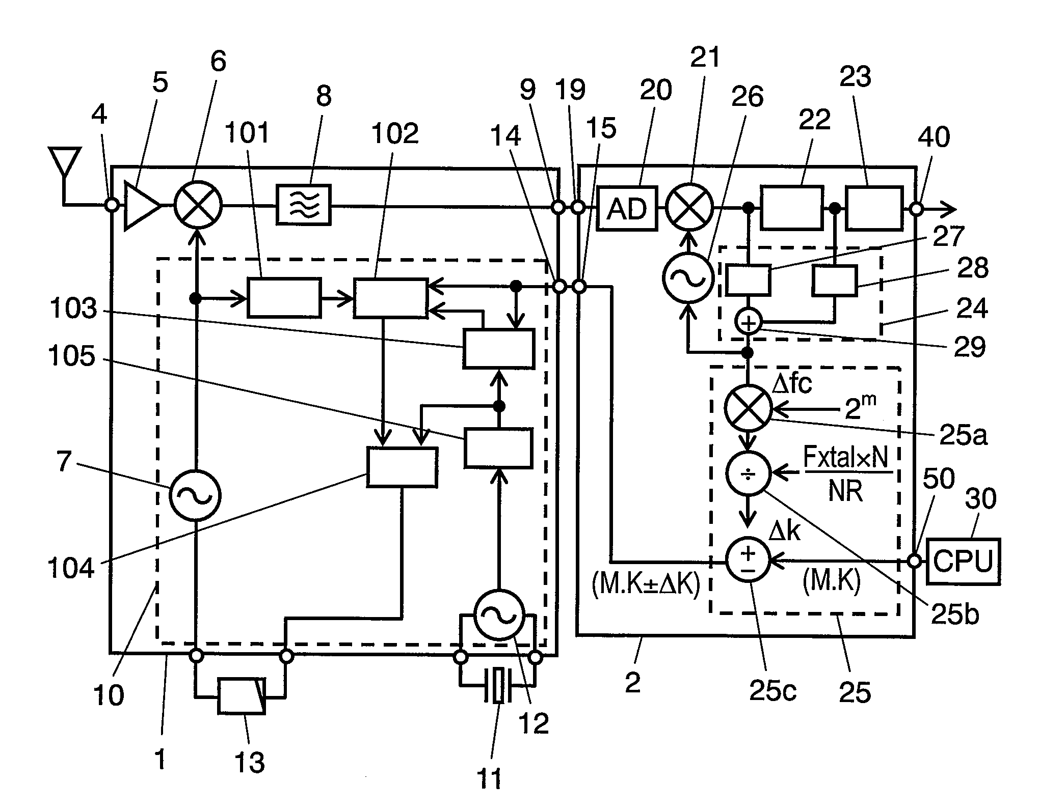
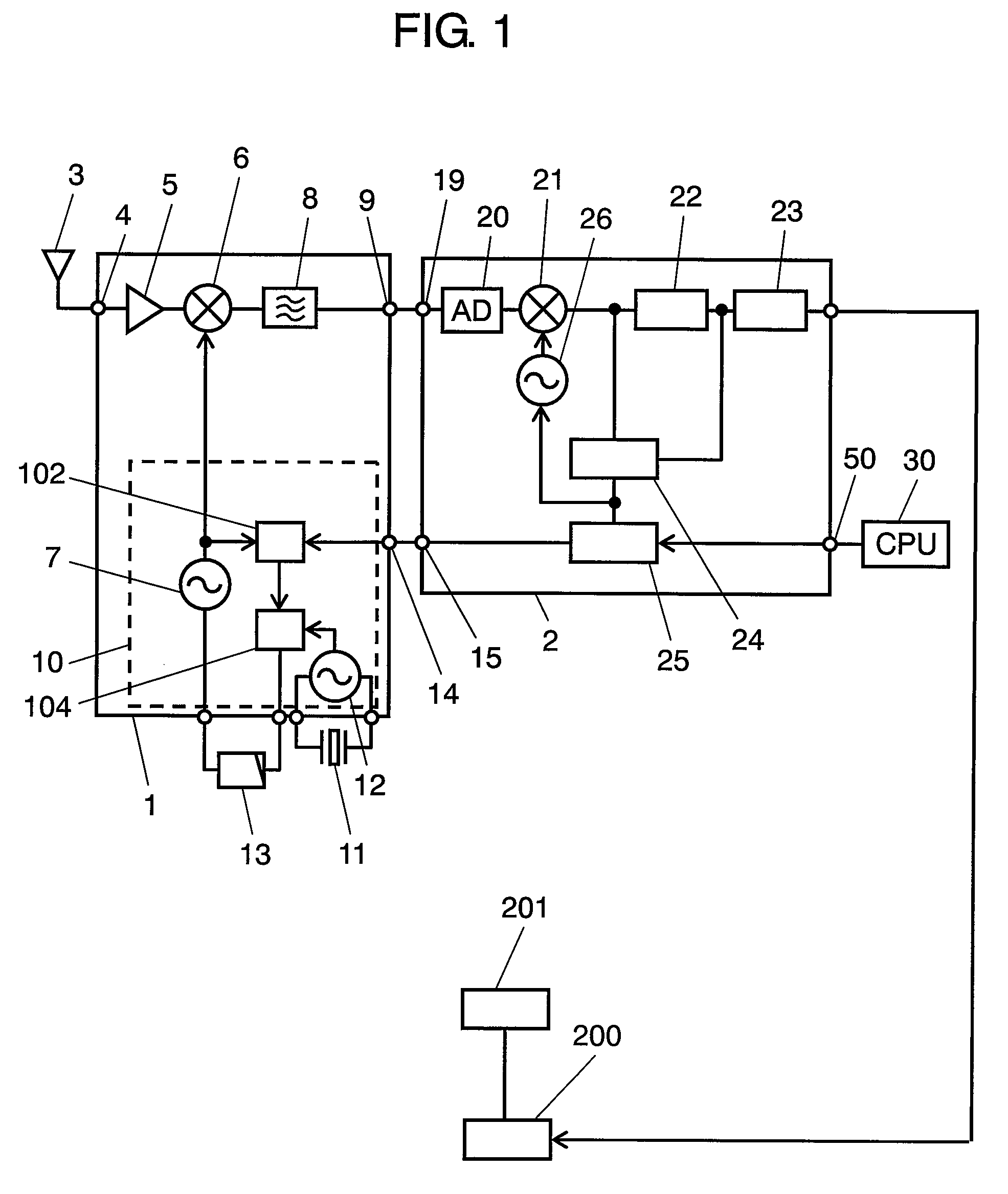
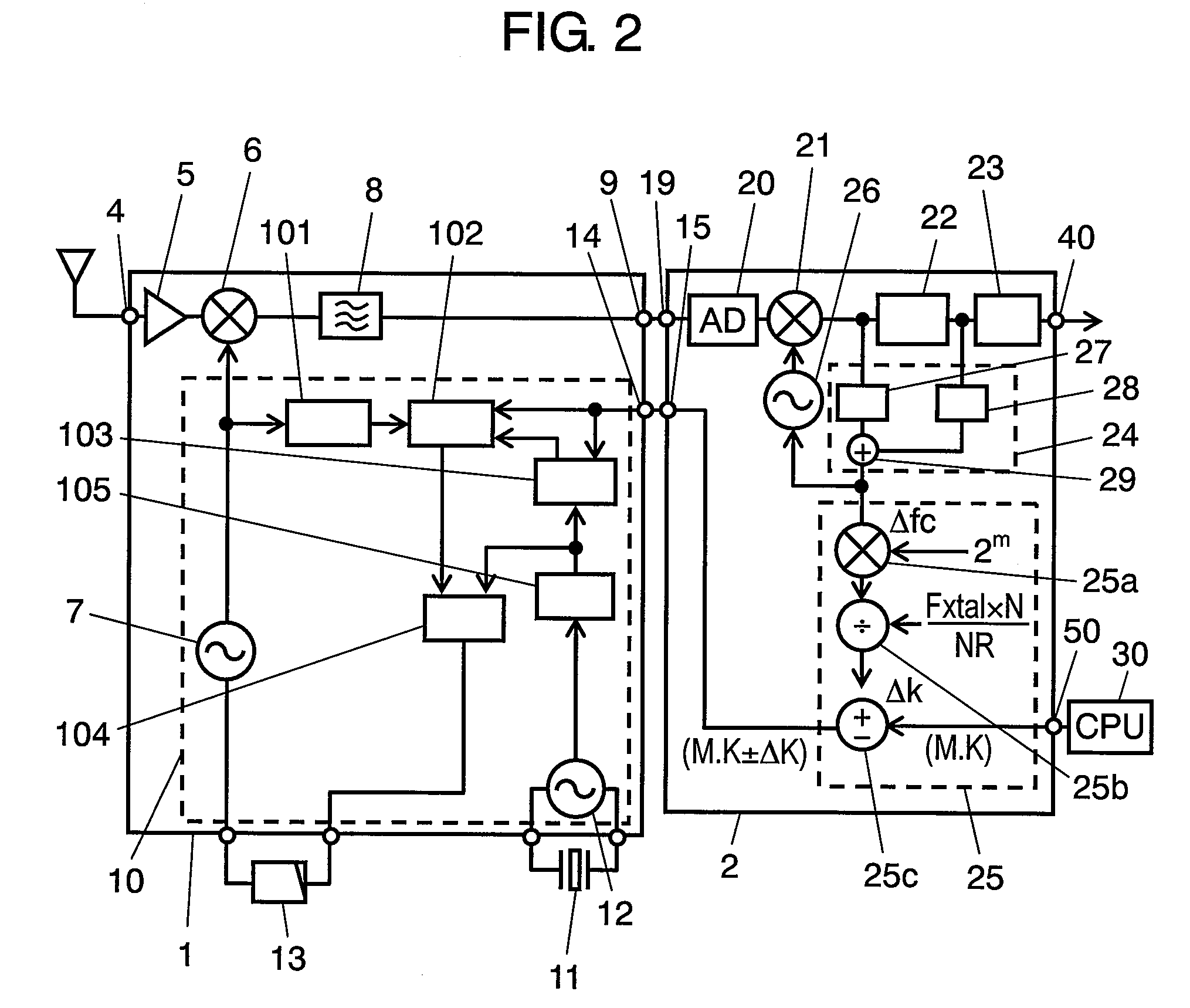
[0082]A receiver of exemplary embodiment 1 of the present invention is described with reference to FIG. 1 and FIG. 2. FIG. 1 is a block diagram of a receiver and an electronic apparatus using it in accordance with exemplary embodiment 1 of the present invention. FIG. 2 is a detailed block diagram of the receiver. The present embodiment describes a case where the receiver receives terrestrial digital broadcasting signals.

[0083]In FIG. 1, the receiver has the following elements:[0084]input terminal 4;[0085]receiving unit 1 connected to input terminal 4;[0086]demodulating unit 2 connected to the output side of receiving unit 1; and[0087]output terminal 40 connected to the output side of demodulating unit 2.

The receiver also has CPU connection terminal 50 for inputting data of CPU 30 for controlling them. An electronic apparatus including the receiver has signal processing unit 200 connected to output terminal 40, and display unit 201 connected to the signal processing unit.

[0088]Receiv...

exemplary embodiment 2

[0178]Exemplary embodiment 2 of the present invention will be described with reference to FIG. 3, FIG. 4A, and FIG. 4B. Unless otherwise noted, exemplary embodiment 2 is similar to embodiment 1.

[0179]The receiver of embodiment 2 employs variable band limiting filter 208 capable of varying the pass band range instead of band limiting filter 8 of embodiment 1.

[0180]FIG. 3 is a block diagram of a receiver in accordance with exemplary embodiment 2 of the present invention. In receiving unit 1 of the receiver of embodiment 2, radio-frequency amplifier 5, mixer 6, and variable band limiting filter 208 for passing IF signals are interconnected in that order and in the direction from input terminal 4 to demodulating unit 2, as shown in FIG. 3. A control signal for controlling the pass band range is fed from data input terminal 14 into variable band limiting filter 208. Data input terminal 14 is connected to CPU 30 via data output terminal 15 and frequency controller 25. Frequency controller...

exemplary embodiment 3

[0190]Exemplary embodiment 3 of the present invention will be described with reference to FIG. 5 and FIG. 6. Unless otherwise noted, exemplary embodiment 3 is similar to embodiment 1.

[0191]Embodiment 3 differs from embodiment 1 in the configuration of frequency error detector 24 and frequency controller 25 in demodulating unit 2. Detection of frequency error Δfc in IF signals or calculation of frequency correction value ΔK based on the frequency error is not always performed.

[0192]FIG. 5 is a block diagram of a receiver in accordance with exemplary embodiment 3 of the present invention. In FIG. 5, demodulating unit 2 of the receiver has memory 60 for primarily storing data between divider 25b and adder-subtracter 25c, derives correction value ΔK of PLL 10 based on the frequency error in the IF signals with frequency controller 25, and primarily stores correction value ΔK in memory 60.

[0193]Operations of the receiver of the present embodiment are described hereinafter in detail.

[0194...


PUM


Abstract

A receiver has a receiving unit including a PLL, a mixer, and a filter, and demodulating unit including a frequency error detector for detecting a frequency error in a signal from a filter. The PLL includes a local oscillator for supplying a local oscillation signal to a mixer, a variable frequency divider for frequency-dividing the local oscillation signal based on a signal from the frequency error detector, and a phase comparator for comparing a signal from the variable frequency divider with a signal from a crystal oscillator. The PLL can reduce the frequency error of the local oscillation signal.

Description

[0001]This application is a U.S. National Phase application of PCT International Application PCT / JP2006 / 311505TECHNICAL FIELD[0002]The present invention relates to a receiver for receiving a signal and an electronic apparatus using it.BACKGROUND ART[0003]Terrestrial digital broadcasting service has been begun, and receivers for receiving the broadcasting service have been developed actively. Japanese Patent Unexamined Publication No. H11-112460 discloses an orthogonal-frequency-division-multiplex (OFDM) signal demodulator that can receive such broadcasting service and shorten the locking time of the frequency synchronization.[0004]A conventional receiver will be described hereinafter with reference to the drawing. FIG. 8 is a circuit block of the conventional receiver. In FIG. 8, the receiver has the following elements:[0005]input terminal 1004;[0006]receiving unit 1001 connected to input terminal 1004;[0007]demodulating unit 1002 connected to the output side of receiving unit 1001;...

Claims


Application Information

Patent Timeline
Patent Type & Authority Patents(United States)
IPC IPC(8): H03D3/24
CPCH03L7/193H04B1/28H03J2200/02H03J2200/07H04L2027/0065H04L27/2657H04L2027/0028H04L2027/0055
Inventor FUJII, TAKESHIOZEKI, HIROAKI
Owner PANASONIC CORP
Why Eureka
Try Eureka