Image heating apparatus and rotatable heating member used for the same

a technology of heating apparatus and heating member, which is applied in the direction of electrographic process apparatus, instruments, optics, etc., can solve the problems of rubber deterioration, damage, and inability to apply sufficient heat to recording materials,

Active Publication Date: 2010-06-08
CANON KK
View PDF15 Cites 28 Cited by
  • Summary
  • Abstract
  • Description
  • Claims
  • Application Information

AI Technical Summary

Problems solved by technology

In the outside heating type, however, a heating unit is not provided in the image forming apparatus, or only the fixing roller is provided with a heating unit.
Accordingly, if the fixing roller and the pressure member have small heat capacity in order to reduce the warm-up time period, the following problems may occur.
For this reason, if the surface of the fixing roller is not heated by the heating unit at a significantly high temperature, a sufficient heat amount may not be applied to the recording material.
For example, even if silicon rubber having high heat resistance is used for the elastic layer of the fixing roller, when the fixing roller is successively used at high temperature of not less than 230° C., rubber is deteriorated and may be destroyed.
In this case, however, if the surface temperature of the fixing roller required for heating and fixing is excessively high, the fixing roller may not be used safely and stably.
For this reason, if heat capacity near the surface of the fixing roller is not appropriate, in addition to internal heat insulation performance and high thermal conductivity near the surface, the fixing roller may not store a heat amount required for heating and fixing toner to the recording material.
However, the expected warm-up time period is so long that heat reaches the inside of the fixing roller, not only the surface thereof.

Method used


Image

  • Image heating apparatus and rotatable heating member used for the same
  • Image heating apparatus and rotatable heating member used for the same
  • Image heating apparatus and rotatable heating member used for the same

Examples


first embodiment

(1) Example of Image Forming Apparatus

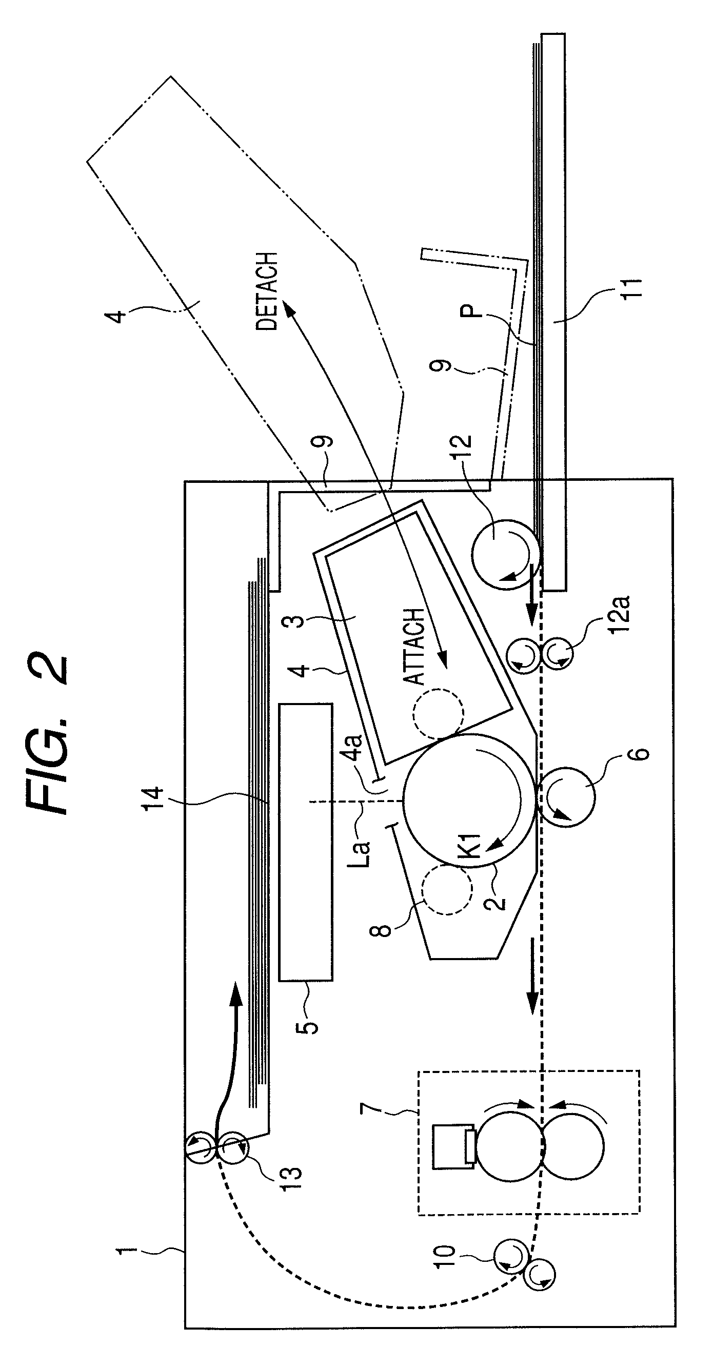
[0057]FIG. 2 is a schematic cross-sectional view illustrating a schematic construction of a laser beam printer (hereinafter, simply referred to as ‘printer’) 1 as an image forming apparatus according to this embodiment.

[0058]The printer 1 receives image information from an image information providing apparatus (not shown), such as a host computer disposed outside the printer 1. The printer 1 performs a series of image forming processes for forming an image on a sheet-like recording material (recording medium) P according to the received image information by a known electrophotographic system.

[0059]The printer 1 includes a process cartridge 4 that holds a drum-shaped rotatable electrophotographic photosensitive member (hereinafter, simply referred to as ‘photosensitive member’) 2 serving as a latent image bearing member, a primary charging mechanism 8, and a developing device 3. Further, the printer 1 includes a laser scanner unit (hereinafter, s...

experiment 1

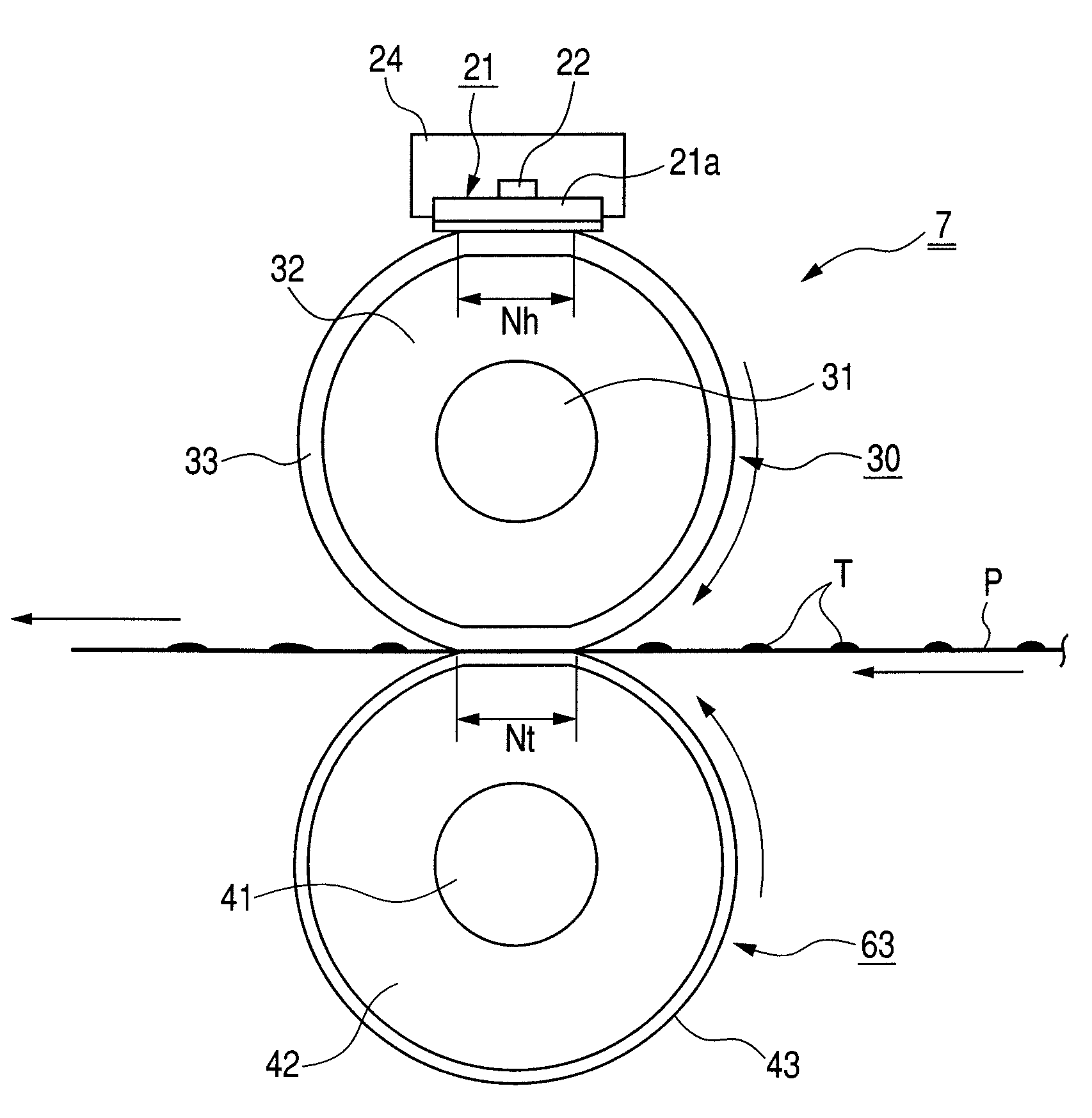
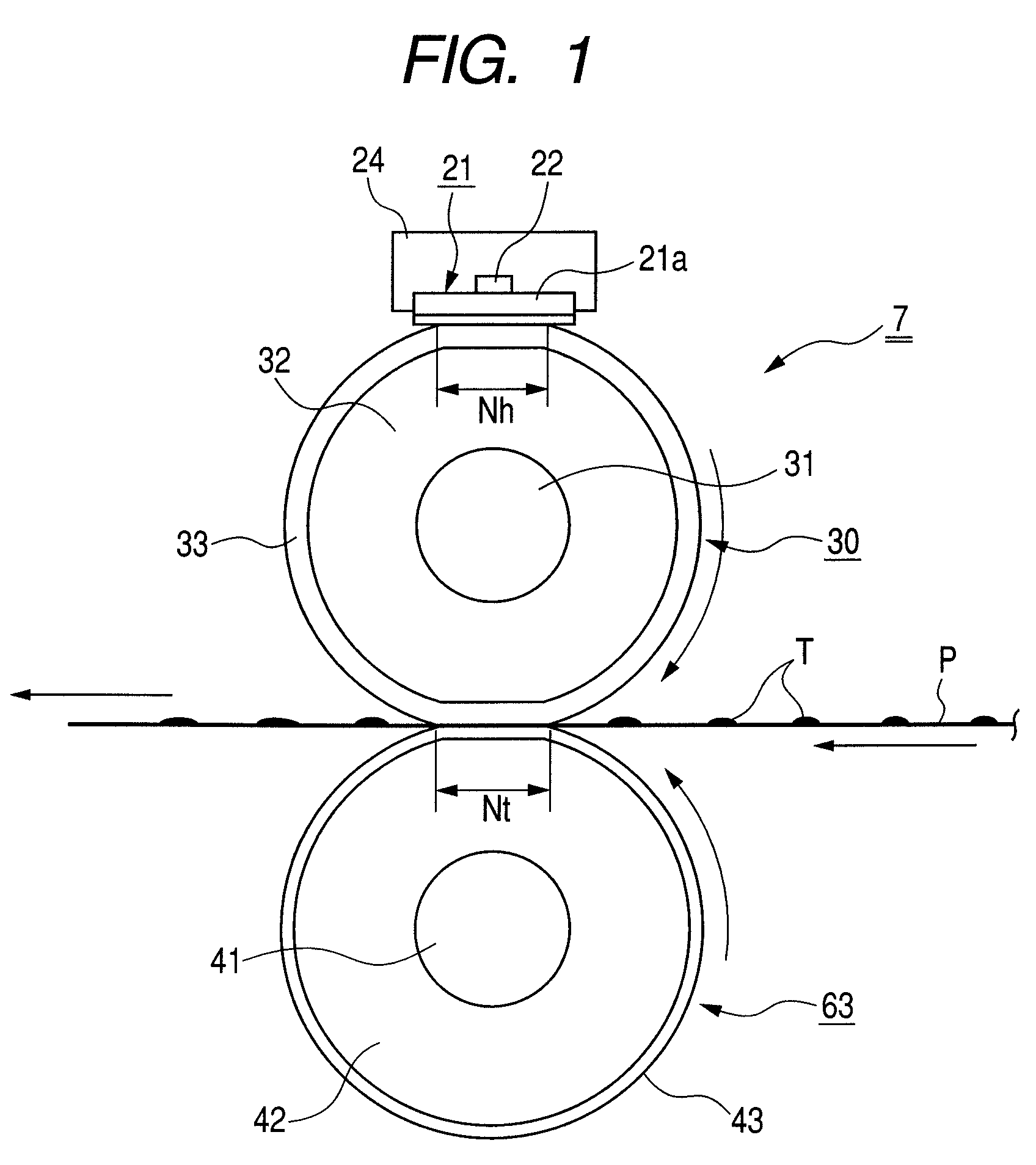
[0174]In the fixing roller 30 used in this experiment, a silicon rubber layer serving as the heat insulating elastic layer 32 having a thickness of 2.0 mm was formed on an SUM core metal 31 having an outer diameter of 8 mm. The silicon rubber layer serving as the heat insulating elastic layer 32 was formed by adding an acrylonitrile balloon as a hollow resin having a particle size of 80 μm to the silicon rubber and mixing triethyleneglycol to connect foams with a small amount. A thermal conductivity of the heat insulating elastic layer 32 was 0.12 [W / (m·K)], and a volume heat capacity thereof was 1.1×10⁶ [J / (m3·K)].

[0175]A silicon solid rubber layer serving as the heat storage layer 33 was formed outside the heat insulating elastic layer 32.

[0176]That is, the fixing roller 30 used in this experiment is a fixing roller including two silicon rubber layers 32 and 33, in which the heat storage layer is formed as the surface layer of the fixing roller. An outer diameter of the fixing rol...

experiment 2

[0201]Next, the heat storage layer 33 of the fixing roller 30 was formed only by changing the thickness of the heat storage layer 33, and a comparative experiment was carried out.

[0202]In this experiment, a fixing roller 30 was used in which a silicon rubber layer serving as a heat insulating elastic layer 32 is formed on an SUM core metal 31 having an outer diameter of 8 mm to have a thickness of 2.0 mm. The silicon rubber layer serving as the heat insulating elastic layer 32 was formed by adding an acrylonitrile balloon as a hollow resin having a particle size of 80 μm to a silicon rubber and mixing triethyleneglycol to connect foams with a small amount. The thermal conductivity of the heat insulating elastic layer 32 was 0.12 [W / (m·K)], and the volume heat capacity thereof was 1.1×10⁶ [J / (m3·K)].

[0203]A silicon solid rubber layer serving as a heat storage layer 33 having a thermal conductivity of 0.3 W / (m·K) and a volume heat capacity of 1.5×10⁶ J / (m3·K) was formed outside the he...


PUM


Abstract

Disclosed is an image heating apparatus. The image heating apparatus includes a rotatable heating member for heating an image on a recording material in a nip portion, and a heating unit for heating the heating member from the outside thereof. With this structure, a warm-up time period or a first print-out time period can be reduced, and low power consumption can be accomplished. Further, satisfactory image quality can be realized with no heating (fixing) irregularity. The heating member has a low thermal conductive elastic layer, and a heat storage layer outside the low thermal conductive elastic layer to have a volume heat capacity larger than the low thermal conductive elastic layer. A heat capacity of the heat storage layer per unit surface area of a fixing member is in a range of 100 J / m2K to 600 J / m2K.

Description

BACKGROUND OF THE INVENTION[0001]1. Field of the Invention[0002]The present invention relates to an image heating apparatus adapted for use as a heat fixing apparatus to be mounted on an image forming apparatus, such as a printer or a copying machine, utilizing electrophotography technology or electrostatic recording technology.[0003]In addition, the present invention relates to a rotatable heating member that is employed by the image heating apparatus.[0004]As such an image heating apparatus, there are a fixing apparatus for fixing an unfixed image on a recording material, a glossiness enhancing apparatus for increasing a glossiness of an image by heating an image fixed on a recording material, and so on, for example.[0005]2. Description of the Related Art[0006]In the image forming apparatus, a fixing apparatus is used in order to heat and fix an unfixed toner image formed and carried on a recording material to the recording material. As such a fixing apparatus, the fixing apparatu...

Claims


Application Information

Patent Timeline
Patent Type & Authority Patents(United States)
IPC IPC(8): G03G15/20
CPCG03G15/2064G03G2215/2019
Inventor NISHIDA, SATOSHIOGAWA, KEN-ICHIKATO, AKIRATAKEDA, ISAMUMATSUNAKA, KATSUHISAABE, ATSUYOSHI
Owner CANON KK
Why Eureka
Try Eureka