
Gait generator of legged mobile robot

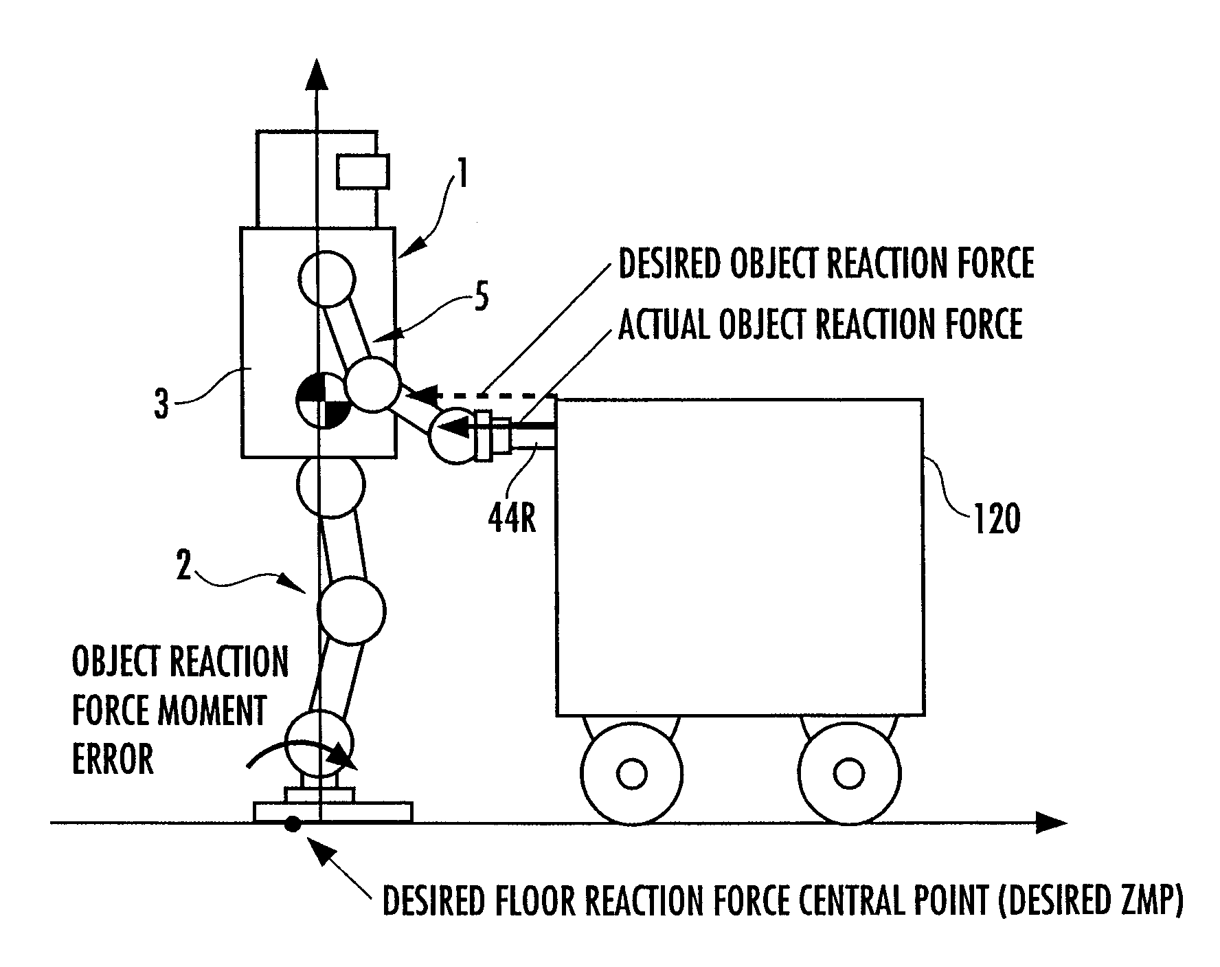
a mobile robot and generator technology, applied in the direction of electric programme control, program control, instruments, etc., can solve the problems of inconvenient generation, generated desired gait actually fails to meet the aforesaid geometric restrictive condition, and achieves the effect of convenient correction processing

Inactive Publication Date: 2010-06-08
HONDA MOTOR CO LTD
View PDF14 Cites 39 Cited by
  • Summary
  • Abstract
  • Description
  • Claims
  • Application Information

AI Technical Summary

Benefits of technology

The present invention provides a gait generator for a legged mobile robot that can generate a desired gait for the robot to move and act on an object while observing the object's movement. The gait generator includes an object dynamic model that represents the relationship between forces and motions of the object, a model manipulated variable determining means to make the object dynamic model close to the actual object's movement, an between-robot-and-object action force provisionally determining means to predict the action force between the robot and the object in a predetermined period, an object motion trajectory provisionally determining means to predict the object's motion trajectory based on the motion of the robot, a restrictive condition determining means to determine if the predetermined geometric restrictive condition is satisfied, and a correcting means to adjust the model manipulated variable and the desired gait parameter to achieve the desired gait. The gait generator ensures accurate prediction of the object's movement and the robot's behavior in the actual movement.

Problems solved by technology

In this case, if the moving plan or the parameters for generating a gait are inappropriate, then a desired gait that fails to satisfy a geometric restrictive condition, such as the one in which the body of the robot does not bump against an object or in which an arm body of the robot to be engaged with the object does not exceed a movable range, may be inconveniently generated.
However, the technology shown in the aforesaid Non-Patent Document 1 is adapted to simulate (predict) a behavior of a robot on the assumption of a certain environmental condition, so that if an actual environmental condition differs from an assumed environmental condition (this situation frequently occurs), then a situation in which a generated desired gait actually fails to satisfy the aforesaid geometric restrictive condition frequently takes place.

Method used


Image

  • Gait generator of legged mobile robot
  • Gait generator of legged mobile robot
  • Gait generator of legged mobile robot

Examples


first embodiment

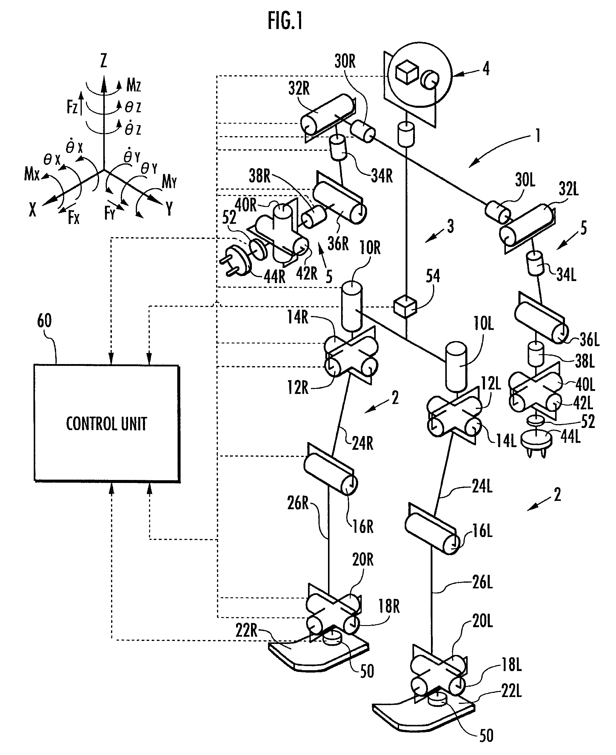
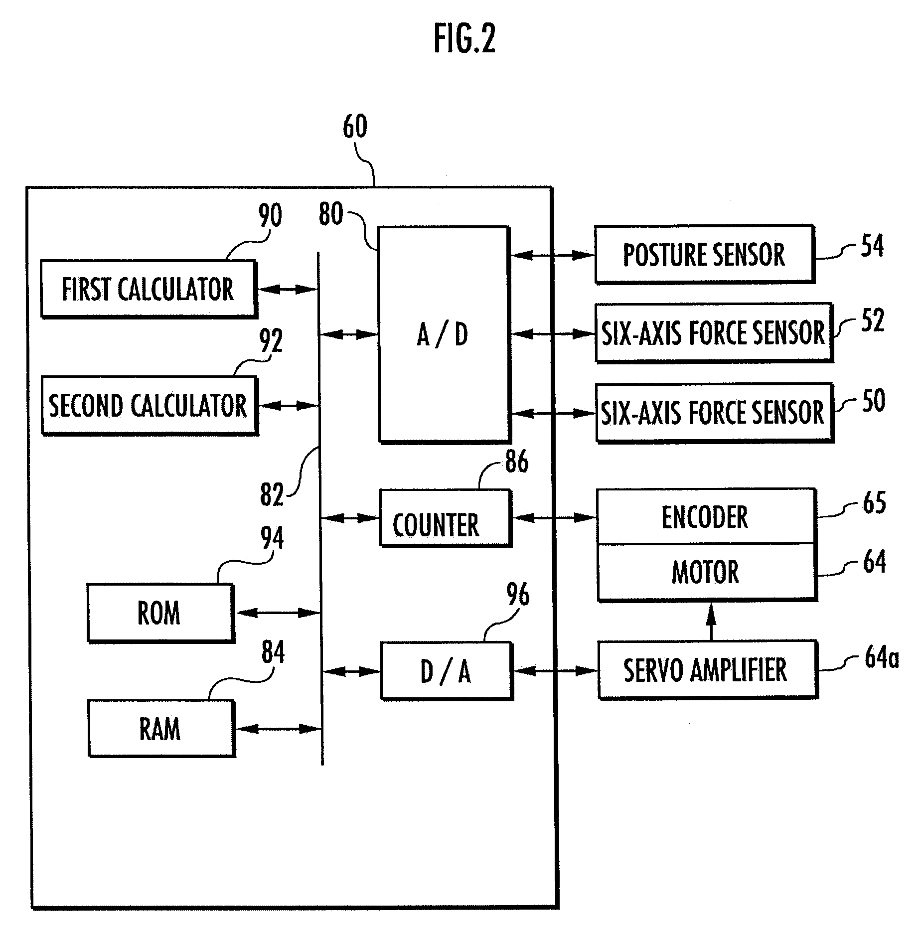
[0072]The following will explain in detail a gait generator 100 according to a first embodiment of the present invention. FIG. 5 to FIG. 7 are flowcharts showing the processing by the gait generator 100. The first embodiment is an embodiment of the first invention, the second invention, and the fourth invention. The arithmetic processing functions of the gait generator 100 constitute the model manipulated variable determining means, the between-robot-and-object action force trajectory provisionally determining means, the object motion trajectory provisionally determining means, the robot gait provisionally generating means, the restrictive condition determining means, and the correcting means in the first invention of the present invention.

[0073]The gait generator 100 sequentially carries out the processing shown in the flowcharts of FIG. 5 to FIG. 7 at a predetermined calculation processing cycle.

[0074]First, in S01, a moving plan for an object 120 is determined. The moving plan to...

second embodiment

[0244]A second embodiment of the present invention will now be explained with reference to FIG. 20 and FIG. 21. In the explanation of the second embodiment, the like components or the like functional portions as those of the first embodiment will use like reference numerals as those of the first embodiment, and the explanation thereof will be omitted. The second embodiment is an embodiment of the first invention, the second invention, and the fourth invention.

[0245]In the aforesaid first embodiment, if a determination result in the aforesaid STEP25 (refer to FIG. 6) is NG, then at least one of the predicted landing position / posture and the desired object motion trajectory has been corrected in S29. In place thereof, according to the present embodiment, if a determination result in STEP25 is NG, then a moving plan is corrected in S29′ such that a geometric restrictive condition at the time is satisfied, as shown in the flowchart of FIG. 20. Then, after the processing in S29′, the pro...

third embodiment

[0249]A third embodiment of the present invention will now be explained with reference to FIG. 22. In the explanation of the third embodiment, the like components or the like functional portions as those of the first embodiment will use like reference numerals as those of the first embodiment, and the explanation thereof will be omitted. The third embodiment is an embodiment of the third invention and the fourth invention.

[0250]In the aforesaid first embodiment, the forward dynamic model shown in FIG. 9 has been used as the object dynamic model used for the calculation processing in S03 (refer to FIG. 5). The present embodiment uses an inverse dynamic model in place of the forward dynamic model, and the present embodiment differs from the first embodiment only in the calculation processing in S03.

[0251]FIG. 22 is a block diagram showing the calculation processing in S03 according to the present embodiment. In the block diagram, the section enclosed by the dashed line corresponds to ...


PUM


Abstract

A gait generator determines a desired motional trajectory and a desired object reaction force trajectory of an object 120 for a predetermined period after the current time by using an object dynamic model while supplying, to the object dynamic model, a model manipulated variable (estimated disturbance force) for bringing a behavior of the object 120 on the object dynamic model close to an actual behavior, and provisionally generates a gait of a robot 1 for a predetermined period by using the aforesaid determined trajectories. Based on the gait and an object desired motion trajectory, a geometric restrictive condition, such as interference between the robot 1 and the object 120, is checked, and a moving plan for the object 120 or a gait parameter (predicted landing position / posture or the like) of the robot 1 is corrected as appropriate according to a result of the check, so as to generate a gait of the robot 1. Thus, a desired gait that satisfies a predetermined geometric restrictive condition related to the interference between the robot 1 and an object is generated by reflecting an actual environmental condition in real time while carrying out the operational control of the robot 1.

Description

TECHNICAL FIELD[0001]The present invention relates to a device for generating a desired gait for causing a legged mobile robot to perform an operation of moving an object while controlling motions of the robot such that the desired gait is followed.BACKGROUND ART[0002]When causing a legged mobile robot, such as a bipedal mobile robot, to perform an operation of, for example, moving a certain object by pushing, the robot is subjected not only to a floor reaction force from a floor with which a distal portion of a leg body thereof is in contact but also to a reaction force from the object. The reaction force received by the robot from the object as described above will be referred to as an object reaction force in the present description.[0003]As a technology for generating a gait of a robot in a state wherein an object reaction force is acting on a legged mobile robot, or for carrying out motion control, there has been known a technology disclosed in, for example, Japanese Patent App...

Claims


Application Information

Patent Timeline
Patent Type & Authority Patents(United States)
IPC IPC(8): G05B13/04
CPCB62D57/032B25J5/00B25J9/16B25J13/00
Inventor HASEGAWA, TADAAKI
Owner HONDA MOTOR CO LTD
Learn More