Universal communications, monitoring, tracking, and control system for a healthcare facility

a technology for healthcare facilities and communications, applied in healthcare resources and facilities, instruments, data processing applications, etc., can solve the problems high pressure, etc., and achieve the effect of high stress, long hours, and high pressur

Inactive Publication Date: 2010-06-08
HILL ROM SERVICES
View PDF161 Cites 125 Cited by
  • Summary
  • Abstract
  • Description
  • Claims
  • Application Information

AI Technical Summary

Benefits of technology

[0003]Caregivers such as physicians, nurses and other staff in a hospital ward, hospital wing, or other healthcare facility generally work under high pressure, high stress and long hours. These caregivers should be highly responsive to patient needs, in non-emergency as well as emergency situations. Due to ever-increasing costs of healthcare and other economic practicalities, efficient deployment of the caregivers in a healthcare facility is desired, particularly at night when the number of caregivers is typically maintained at a minimum. Nevertheless, optimizing efficiency is of secondary importance relative to the primary objective of providing a high level of healthcare. Accordingly, it is desirable to increase the efficiency of caregivers and improve the healthcare provided to patients.

Problems solved by technology

Caregivers such as physicians, nurses and other staff in a hospital ward, hospital wing, or other healthcare facility generally work under high pressure, high stress and long hours.

Method used


Image

  • Universal communications, monitoring, tracking, and control system for a healthcare facility
  • Universal communications, monitoring, tracking, and control system for a healthcare facility
  • Universal communications, monitoring, tracking, and control system for a healthcare facility

Examples


Embodiment Construction

[0013]While the invention is susceptible to various modifications and alternative forms, exemplary embodiments thereof have been shown by way of example in the drawings and will herein be described in detail. It should be understood, however, that there is no intent to limit the invention to the particular forms disclosed, but on the contrary, the intention is to cover all modifications, equivalents, and alternatives falling within the spirit and scope of the invention as defined by the appended claims.

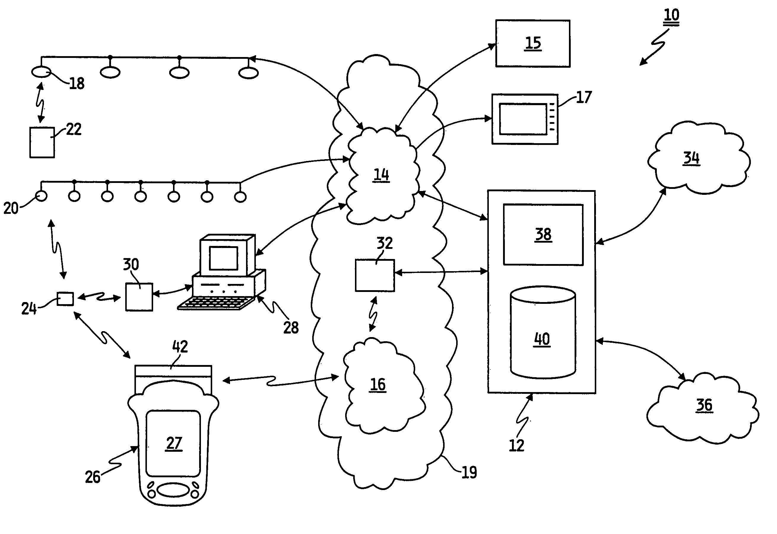
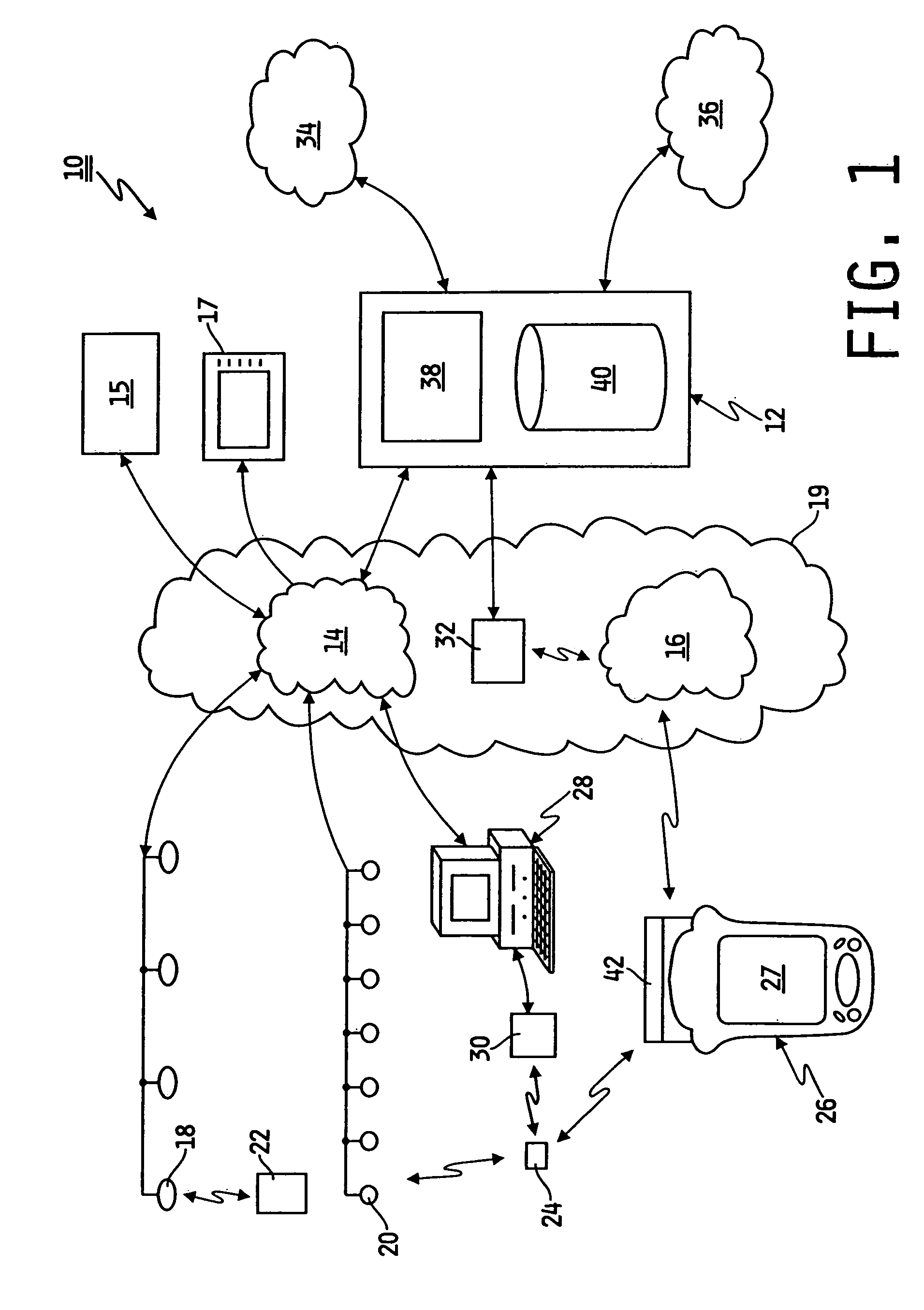
[0014]FIG. 1 shows components of a system according to one embodiment of the present invention. System 10 of FIG. 1 generally includes a server 12, a first network 14, a second network 16, a plurality of first transceivers 18 connected to first network 14, a plurality of second transceivers 20 connected to first network 14, a plurality of active tags 22 (only one shown), a plurality of passive tags 24 (only one shown), a plurality of client devices 26 (only one shown), a plurality of ...


PUM


Abstract

A system for a facility including a server coupled to a database, a plurality of tags coupled to a plurality of assets, each tag being configured to transmit a tag ID that is uniquely associated in the database with data describing the asset, a plurality of first transceivers for receiving tag IDs and transmitting the tag IDs and a transceiver ID to the server, which is configured to update the database with location information for the asset to indicate that the asset is adjacent the transceiver, and a plurality of portable client devices configured to wirelessly transmit to the server a client device ID that is uniquely associated in the database with a user of the client device, whereby, in response to receipt of the client device ID, the server is configured to update the database with location information for the user to indicate a location of the user.

Description

CROSS-REFERENCE TO RELATED PATENT APPLICATIONS[0001]This application claims the benefit of U.S. Provisional Patent Application Ser. No. 60 / 414,057, filed Sep. 27, 2002 which is hereby expressly incorporated herein by reference.TECHNICAL FIELD OF THE INVENTION[0002]The present invention relates generally to monitoring systems for improving communications and personnel and asset management in a healthcare facility.BACKGROUND AND SUMMARY OF THE INVENTION[0003]Caregivers such as physicians, nurses and other staff in a hospital ward, hospital wing, or other healthcare facility generally work under high pressure, high stress and long hours. These caregivers should be highly responsive to patient needs, in non-emergency as well as emergency situations. Due to ever-increasing costs of healthcare and other economic practicalities, efficient deployment of the caregivers in a healthcare facility is desired, particularly at night when the number of caregivers is typically maintained at a minimu...

Claims


Application Information

Patent Timeline
Patent Type & Authority Patents(United States)
IPC IPC(8): G06Q10/00G06Q50/00G06F15/16G06F17/30G06F19/00G06Q50/22
CPCG06Q50/22G06F19/327G06F19/323G06F19/3462G16H10/65G16H40/20G16H40/40G16H40/67
Inventor WILDMAN, TIMOTHY D.RILEY, CARL W.MCNEELY, CRAIG A.FLECK, THOMAS M.GALLANT, DENNIS J.HUSTER, KEITH A.
Owner HILL ROM SERVICES
Why Eureka
Try Eureka